Creating a massing model
|
Tool |
Tool set |
|
Massing Model
|
Site Planning |

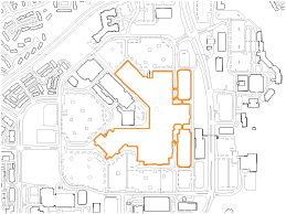
The Massing Model tool creates a building shell for illustrative purposes. This is an easy way to create a representative or context building when a detailed building is not required. Building models can also be created by drawing a closed 2D shape and then selecting the Create Objects from Shapes command (see Creating objects from shapes). A massing model can be a site modifier.
To create a massing model:
Click the tool.
The Massing Model tool and Campanile tool share the same position on the tool set. Click and hold the mouse on the visible tool to open the pop-out tools list (see Pop-out tools) and select the desired tool.
Using the polyline creation modes, click to begin drawing the outline of the building. Continue clicking to draw the shell polyline. Double-click, or click once at the start point, to end the polyline. The first time you use the tool in a file, a properties dialog box opens. Set the default parameters. The parameters can be edited later from the Object Info palette.
Click to show/hide the parameters.Click to show/hide the parameters.
|
Parameter |
Description |
|
Name |
Enter a building name for labeling |
|
Show in Plan |
Select whether to show the building roof or footprint in Plan view |
|
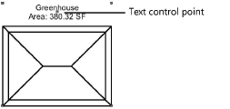
Label |
Select a text label, if any, for the building shell in Plan view; move the text control point to reposition the text
|
|
Overall Wall Height |
Specifies the building height (to the eave) |
|
Floor Count |
Specifies the number of floors in the building; a slab is drawn for each floor |
|
Opens the Floor Setting dialog box, to set the appearance and the usage of floors; see below |
|
|
Wall Class |
To control appearance, select a class to use for wall attributes and textures from the list of classes present in the drawing, or create a new class |
|
Use custom roof from profile |
Creates a custom roof. The first roof created by the object is used as the default custom roof; if the number of stories has changed, the height of the custom roof needs to be manually adjusted. |
|
Roof Overhang |
Specifies the distance the roof extends from the building |
|
Roof Thickness |
Indicates the roof thickness |
|
Roof Class |
To control appearance, select a class to use for roof attributes and textures from the list of classes present in the drawing, or create a new class |
|
Pitched roof |
Adds a roof to the building shell |
|
Eave Style |
Select an eave style from the list |
|
Roof Slope |
Specifies the roof pitch angle in degrees |
|
Draw floors |
Draws floors in the building |
|
Slab Thickness |
Specifies the floor thickness |
|
Display shadow in plan view |
Displays a shadow based on the roof outline in Top/Plan view. Document-wide settings from the Plan Shadows pane on the Document Preferences dialog box are applied. Click Shadow Settings to open the Document Preferences dialog box to review and edit the settings (see Document preferences: Plan Shadows tab). |
|
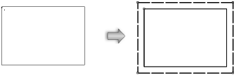
Use site modifiers |
Adds a pad and grade limits to the base of the building and allows the building to modify the site model |
|
Use grade limits |
Uses grade limits to define the site modifier modification area |
|
Grade Limits Offset |
Sets the offset of the grade limits from the massing model |
|
Gross Area |
Displays the gross area value for all the floors |
|
Vertex parameters |
Edits the object vertices. See Editing vertex-based objects. |
If the massing model is used as a site modifier, the proposed site model requires updating. Select the site model and click Update from the Object Info palette.
Massing model floor settings
Control the height, appearance, and usage of massing model floors to make peripheral buildings on a site plan more closely mimic real conditions. You can use different heights, attributes/textures, and usage data for each floor, to provide a general indication of the building's function and appearance, such as for a mixed use building with retail on the ground floor and residences above.
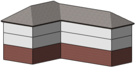
A massing model with individual floor heights has a taller ground floor for retail space, and two shorter upper floors for residential usage. Slab thickness set equal to floor heights allows each floor to have a texture applied to the entire wall.
Click to show/hide the parameters.Click to show/hide the parameters.
|
Parameter |
Description |
|
Overall Wall Height |
Specifies the building height (to the eave); this value automatically adjusts to accommodate all the individual floor heights |
|
Floor Count |
Specifies the number of floors in the building |
|
Allow individual floor heights |
By default the overall wall height is divided by the number of floors to create floors of the same height; select to create floors of different heights |
|
Set slab thickness equal to floor heights |
Allows each floor's slab to cover the entire wall surface. When selected, the textures applied to each slab control the appearance of the whole wall for the floor. |
|
Slab Thickness |
If the slab thickness isn't set equal to floor heights, enter the thickness |
|
List of floors |
Click a row from the list and set its parameters below. Elevation and Floor Height are available only if individual floor heights are allowed; otherwise the fixed values are displayed. |
|
Class |
To control the appearance of the slab, or of the entire floor's wall surface if slab thickness is set to floor height, select a class from the list of classes present in the drawing, or create a new class. Select <Massing Model Class> to place the floor in the same class as the massing model object. |
|
Elevation |
If individual floor heights are allowed, enter the floor's elevation, or allow it to be set automatically as the floor heights of the floors below are entered |
|
Floor Height |
If individual floor heights are allowed, enter the floor's height |
|
Usage Data |
If desired, enter the floor's use. This is useful in worksheets, for example, when reporting the usage data of the floors using the 'Floor Usage Data' parameter (see Worksheet functions). |