Set up your drawing environment
You can control a variety of settings to make your drawing environment look the way you want, from whether to use dark or light mode, to controlling the colors of highlights and other visual cues in the software, placement of the various palettes, and even which drawing aids such as the internal origin marker, 2D and 3D axes, grids and more show in the drawing area.
Quick preferences
The Quick Preferences menu, accessed on the far right of the Tool bar  , provides an easy and convenient way to enable or disable the most commonly used Vectorworks, document, and interactive preferences, and a few frequently used commands. For further convenience, you can pin the quick preferences you change the most to the Tool bar. You can also open both the Vectorworks Preferences and Document Preferences dialog boxes from the bottom of the Quick Preferences menu.

Work in dark or light mode
A combination of Vectorworks preferences controls whether all of Vectorworks, or only some portions, is set to dark or light mode.
To set Vectorworks to dark or light mode, or to match the system setting, open the Vectorworks preferences General pane. In the Appearance section, select which mode to use. This setting controls the Vectorworks user interface - the framework that contains all the commands and tools, the palettes, and dialog boxes, but not the drawing area itself. If you're using dark mode, you may also want to select Use dark background for dialog box preview images. This setting makes the preview images that display in some dialog boxes, like Window Preferences, display dark, too. Otherwise, the previews in dark dialog boxes will display with a white background, which may be jarring.
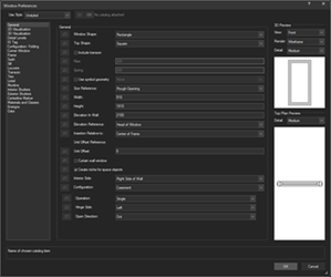
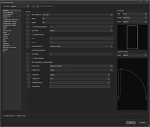
Use dark background for dialog box preview images is not selected (left); Use dark background for dialog box preview images is selected (right)
Next, still on the General pane, go to the Document Window section. To make the background of the drawing area itself dark, select Use dark background. This setting also changes the default colors used for visual cues in the drawing area to the Dark Background defaults. These colors can be customized. You can toggle the dark background on/off in quick preferences as you work.
Resize user interface elements
You can adjust the size of user interface elements in the main application window, such as graphic icons, text and buttons in the View bar, Tool bar, tool sets, palettes, and objects in the drawing window, such as screen cues, the floating Data bar, Quick Search and Smart Options Display so they fit your comfort level. On Mac, select the option you want under Control Sizes on the Vectorworks preferences General pane. Use the operating system settings to adjust these on Windows.
Place the palettes
The versatility of palettes in Vectorworks lets you organize elements and tools according to your preferences to get the most out of your available workspace. Palettes can be resized, hidden, docked, detached, and repositioned. You can modify individual tabs in multiple-tab palettes to give you more control over what you need and use most often. Special features for tool palettes, title bar controls, and autosave abilities give you even more options.
Customize application colors
You can change the colors, and in some cases the opacity and size, of the drawing area background and the interactive visual cues that display as you work, including highlights, previews, SmartCursor and snapping hints, the Onscreen View Control, and more. Vectorworks provides a set of default colors for use with a light background and another for use with a dark background. Any of the items can be changed to meet your needs.
To change the appearance of the drawing area and items that display in it, open the Vectorworks preferences Interactive pane, and then click Interactive Appearance Settings. The Interactive Appearance Settings dialog box is divided into Light Background and Dark Background tabs, to be used when working in light or dark mode. Each tab lists all the interactive elements you can change. Click an element, and change the settings on the right side of the dialog box.
Pin to the View bar
Located right along the top of the application window, the View bar gives you quick access to tools and options that control how your drawing displays. Decide which options you want to display and click a group's pin icon in the View bar settings  to add or remove it from the View bar.
Show or hide drawing orientation indicators
You can set up Vectorworks to show the orientation, navigation, and coordinate tools you find useful, and hide the others to reduce visual clutter.
3D and Top/Plan axes
To show or hide the 3D axes, double-click the Snap to Grid button on the Snapping set, and turn Show 3D axes on or off. If 3D axes are shown, you can further opt whether to show the Z axis (or only the X and Y axes), and whether to include axis labels.
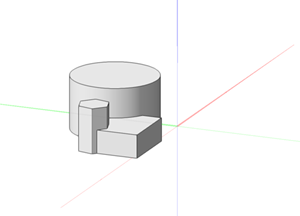
When Show 3D axes is selected, you can opt whether to show the X and Y axes in Top/Plan view. On the Vectorworks preferences Display pane, select whether to Show colored axes in Top/Plan view.
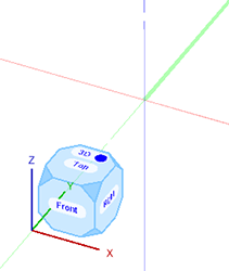
When you show 3D axes in the drawing area, you can still show or hide them from any view. Hover in the corner with the Onscreen View Control (lower left by default), and click the menu button  that displays to open the popover. With the Onscreen View Control shown, select Show axes.
The working plane
When drawing in 3D views, the working plane can be set to any orientation, to provide snapping points and help to place geometry accurately. It shows in 3D views by default, but if you need a cleaner view, you can hide it from the Working Planes palette.
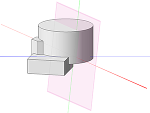
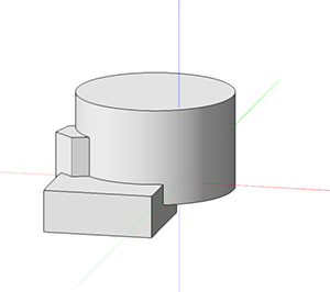
Working plane shown on left; working plane disabled on the right
Grid, page boundary, and rulers
Toggle the grid, page boundary, and/or rulers on or off in quick preferences. You can further control the appearance of the grid in the Document Setup dialog box, the page boundary in the Page Setup dialog box, and rulers in the Vectorworks preferences General pane.
Internal origin marker
Vectorworks has both an internal origin and a user origin. A new file's internal origin is a built-in reference point, and is always set at the fixed coordinates of 0,0. Internal origins are useful for maintaining precision when coordinates are large. The user origin is a user-created reference point, and may or may not be at the same coordinates, especially for imported files or when working with a large site. User origins are a good way to align coordinates with your project requirements without moving the geometry. Although you can choose whether to show or hide the internal origin marker, we recommend you show it in most circumstances. On the Vectorworks preferences Display pane, select whether to Show internal origin marker.
Set rendering DPI for sheet layers
The resolution Vectorworks uses when printing objects depends on a few different settings, which vary by layer type and printing preferences. You can edit a selected sheet layer's properties in the Sheet Layers tab of the Organization dialog box. A DPI of 72 is fine for drafting sheets, with at least 300–500 DPI as a minimum for high-quality output. A higher DPI is better for a high-quality output of images, rendered viewports, and similar needs.