Creating 2D components for symbol definitions and plug-in objects
For symbols and some plug-in objects, 2D components can be shown in hidden line rendered viewports to present a more appropriate image. See Concept: 2D components for symbol definitions and plug-in objects. You must select Display 2D Components when creating viewports or on the Object Info palette for each viewport, or only 3D components will display.
Some symbol definitions already have 2D components, and 2D components can be created for symbol definitions that do not already have them. Likewise, a plug-in object may provide some 2D components, and depending on the object, the plug-in author may allow the user to alter the existing components or add new ones.
In some cases, such as dimension objects, altering the plug-in object would break the functionality. Plant objects have their own workflow for plant styles and do not use this procedure.
For plug-in objects, 2D components you create do not update automatically when the plug-in object is edited; if the plug-in object changes, manually update the 2D components to match the changes, or see Deleting user-provided 2D components of plug-in objects to preserve the plug-in object workflow. Plug-in generated 2D components do update automatically when the plug-in object is generated.
For symbol definitions, any time the 3D geometry is edited, all affected 2D components must also be changed to maintain a consistent appearance.
To create 2D components for a symbol definition or plug-in object:
Do one of the following:
To edit a symbol definition or plug-in object style, locate the resource in the Resource Manager, and then right-click on it and then select Edit 2D Components from the context menu.
To edit a plug-in object instance in the drawing, right click on the object and then select Edit 2D Components from the context menu.
You can also right-click on a symbol instance in the drawing; however, this method edits the symbol definition. A single symbol instance cannot be edited.
The object opens in Object editing mode.
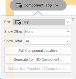
When editing the components of symbol definitions and plug-in objects, a Component button and edit options popover displays; click on the Component button to hide or display the edit options popover. Click anywhere outside of the edit options popover to hide the popover. More parameters are also available in the Object Info palette.
|
2D Component edit options |
Description |
|
Edit |
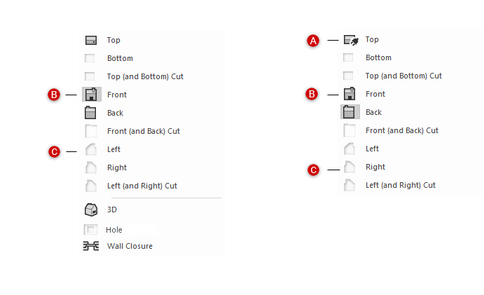
From the list of available components for the object, select the component to edit. For both symbol definitions and plug-in objects, six 2D planar views and three cut views are available for editing. For symbols, 3D components, hole components, and wall closures are also available from the palette. Icons in the list indicate whether the current 2D component for each view is user-provided (custom), empty, or plug-in generated (plug-in objects only).
Components for symbol definitions (left), and components for plug-in objects (right); only plug-in generated components update automatically if the plug-in object is edited
A: A plug identifier on the component icon indicates it is plug-in generated B: An icon indicates a component has been provided C: No icon indicates the component is empty |
|
Show Other |
Displays a relative component grayed in the background. This view, which is used as a reference for creating and placing graphics in the active component view, can be snapped to but not selected. The available views depend on the component selected in Edit. If the component opposite the Edit component is selected, it displays mirrored. If there is not yet a component available for the selected option, the editing area appears empty. |
|
Show Detail |
Select the detail level to display the active component view; this can be used to view the results when Customizing detail levels for 2D and 3D components of symbol definitions and plug-in objects |
|
Edit Component Location |
Opens a nested object editing mode with a plane that displays the current location of the selected component’s plane, for relocation; see Relocating 2D components of symbol definitions and plug-in objects |
|
Generate from 3D Component |
Generates 2D geometry for the component from the contents of the 3D component |
|
Delete User-Provided 2D Components (Plug-in objects only; available when user-provided 2D components are present) |
Opens the Delete User-Provided 2D Components dialog box, so you can select which custom 2D components to delete; see Deleting user-provided 2D components of plug-in objects |
Click the Component button, and then select the component to edit on the edit options popover.
For objects with opposite sides that are mirror images, such as the left and right side of a toilet fixture, there is no need to create a 2D component for both views. Select Mirror opposite view graphics for empty 2D Components in the Create Symbol dialog box or Symbol Options dialog box for symbol definitions (see Creating symbol definitions), or in the Plug-in Object Style Options or Plug-in Object Options dialog box for plug-in styles or instances (see step 2).
Select the desired Show Other view and Show Detail level to use as visual aids.
Optionally, select Generate from 3D Component from the edit options, and select the line rendering style for the 2D component from the Generate 2D Graphics from 3D Component dialog box.
2D components generated from 3D components are considered user-provided. For plug-in objects, these 2D components do not update automatically when the plug-in object is edited; if the plug-in object changes, manually update the 2D components to match the changes, or see Deleting user-provided 2D components of plug-in objects.
The 2D component for the selected view is created as a group and correctly aligned with the other components. You can edit the group or ungroup the component for editing.
Draw lines and shapes on the screen plane to either create or edit the 2D component as needed. Be careful to align the 2D components correctly with the 3D components and other component views for correct display in a viewport. In addition to the object editing capabilities available for any object in Vectorworks, it is possible to relocate the component location or display different detail levels, as needed for correct presentation.
If you're creating 2D components for a plug-in object style or plug-in object instance, see Additional plug-in object style and instance options to set how 2D components display for the object.
