The 2D Polygon tool creates open and closed polygons with single lines. Polygons can have as few as three vertices or as many as 32,767 vertices. The 2D Polygon tool can also automatically create polygons by filling or outlining existing geometry, to easily annotate a drawing graphically by outlining, filling, or texturing (with an image or gradient fill) the new polygons.
Three modes are available. The Push/Pull toggle mode is available in 3D views for instantly extruding the polygon after creation.
Mode |
Description |
|
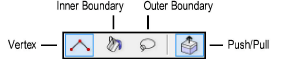
Vertex |
Creates a polygon by clicking to set each vertex |
|
Inner Boundary |
Creates a polygon out of existing geometry by clicking within the boundary of an object |
|
Outer Boundary |
Creates a polygon out of the outer boundary of existing geometry by defining geometry with a lasso marquee |
|
Push/Pull (3D views only) |
Instantly extrudes the polygon after creation; available in 3D views |

To create a single-line 2D polygon:
1. Click the 2D Polygon tool from the Basic palette, and select Vertex from the Tool bar.
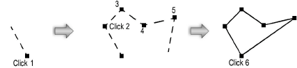
2. Click to set the polygon’s start point (first vertex).
3. Click at each vertex.
4. Double-click at the final vertex to end an open polygon, or click at the starting vertex (a point cue displays) to end a closed polygon (the first and last vertex are automatically joined).
Alternatively, after completing all but the final click, press the keyboard shortcut (K by default) to automatically close the polygon. The shortcut also closes path-based objects that function similarly to the Polygon tool. See Modifying Snapping and Mode Shortcuts to change the shortcut.
When drawing a 2D polygon or path-based object, move the mouse in the direction of the next-to-last click and press the shortcut key before clicking; the software extrapolates the correct alignment and position for a 90° corner and places the final two clicks to complete the shape.
The 2D Polygon tool can create a new polygon based on the inner boundary of existing geometry. Existing geometry refers to visible objects and solids in the active layer (within the active working plane) or the viewport cache of a hidden-line rendered viewport in Edit Annotation mode. The stacking order of the 2D objects does not apply; objects that are overlapped by other objects can still have their boundaries considered. If the object is a polyline (open or closed), a polygon with holes, or is curved, a polyline is created instead of a polygon.
Polygons cannot be created from symbols. Convert the symbol to a group, and then ungroup.

To create a 2D polygon from the inner boundary of existing geometry:
1. Click the 2D Polygon tool from the Basic palette, and select Inner Boundary from the Tool bar.
If desired, set the attributes in the Attributes palette (fill style, pen style, line and line endpoint style). The attributes of the polygon can also be specified after creation.
2. Click over one or more objects to create a polygon based on the inner boundary of the 2D objects and/or faces of solids in the active plane. Different methods of using the 2D Polygon tool will achieve different results.
Modification |
Method |
|
Create a polygon |
Click to place the polygon |
|
Add to a polygon as it is created |
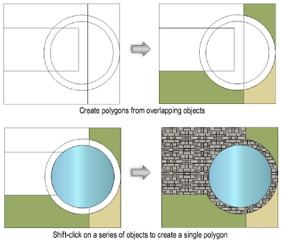
Press the Shift key while clicking over existing adjacent geometry to add to the polygon |
|
Apply the attributes of an existing object to the new polygon |
Select the existing object and press the Option key (Mac) or the Alt key (Windows) while clicking to create the new polygon(s) |
To speed up the polygon fill for complex images, zoom in on the area first.
The polygon overlays the existing geometry, and the original objects are unchanged
Another way to create planar objects from faces is with the Extract Surface mode of the Extract tool. See Extracting Geometry.
The 2D Polygon tool can create a polygon based on the outer boundary of existing geometry. Existing geometry refers to visible objects in the active layer (within the active working plane) or the viewport cache of a hidden-line rendered viewport in Edit Annotation mode. The stacking order of 2D objects does not apply; objects that are overlapped by other objects can still have their boundaries considered. If the object is a polyline (open or closed), a polygon with holes, or is curved, a polyline is created instead of a polygon.
Polygons cannot be created from symbols. Convert the symbol to a group, and then ungroup.

To create a 2D polygon from the outer boundary of existing geometry:
1. Click the 2D Polygon tool from the Basic palette, and select Outer Boundary from the Tool bar.
If desired, set the attributes in the Attributes palette (fill style, pen style, line and line endpoint style). The attributes of the polygon can also be specified after creation.
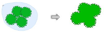
2. Click in the drawing and drag to create the lasso marquee. A polygon is created based on the outer boundary of any 2D objects on the active plane completely enclosed within the marquee. Alternatively, press the Option key (Mac) or Alt key (Windows) while creating the marquee, and the polygon is based on the outer boundary of any co-planar 2D objects that are encountered by the marquee.
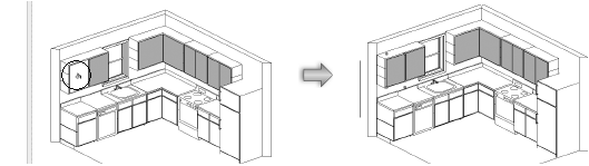
The creation of polygons based on the inner and outer boundaries of existing geometry is very useful for graphically annotating the elements of a sheet layer viewport that is rendered with hidden line rendering. (Sheet layer viewports are described in Creating Sheet Layer Viewports.)

To create a 2D polygon from the inner/outer boundary of existing geometry in a viewport:
1. Create a sheet layer viewport from a design layer as described in Creating a Sheet Layer Viewport from a Design Layer.
2. For the Rendering mode of the viewport, select Hidden Line. Update the viewport rendering by clicking Update from the Object Info palette.
3. Edit the viewport in annotation mode by selecting Modify > Edit Viewport.
The Edit Viewport dialog box opens. Select Annotations and Display Viewport Cache.
4. Click OK to enter viewport annotation mode.
5. Click the 2D Polygon tool from the Basic palette, and select Inner Boundary or Outer Boundary from the Tool bar.
If desired, set the attributes in the Attributes palette to the desired fill settings (Fill Style, Pen Style, Line and Line Endpoint Style). The attributes of the polygon can also be specified after creation.
Apply an image fill to the polygon to simulate a texture (see Using Image Fills).
6. Because the viewport is rendered with hidden line and the viewport cache is used for annotations, any of the objects in the drawing can be used as the basis for new polygons. If in Inner Boundary mode, click the paint bucket cursor on the desired drawing objects. If in Outer Boundary mode, create a lasso marquee to include the desired objects. A 2D polygon is created based on the inner or outer boundary of the geometry.
The 2D Polygon tool works on 2D objects in the design layer. It does not apply to 2D objects or annotations that have been added to the sheet layer.
7. Click Exit Viewport Annotation at the top right corner of the drawing window to return to the sheet layer.
An alert dialog box may ask if keeping the viewport cache is necessary. The viewport cache can be removed, if desired, as it is no longer necessary for creating the polygons.
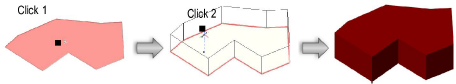
A planar polygon that has been created in a 3D view can be extruded immediately after creation.

To extrude a created polygon:
1. Enable the Push/Pull toggle mode in the Tool bar for the Polygon or Regular Polygon tool.
2. Create a polygon using any of the modes in the Tool bar.
3. With the polygon still selected, click, move the cursor, and then click to create the extrude.
A polygon can be extruded at any time with the Push/Pull tool. See Direct Modeling with the Push/Pull Tool.
The extrude height can be changed with the Reshape tool (see Reshaping Extruded Objects and Solid Primitives), or modified in the Object Info palette.
~~~~~~~~~~~~~~~~~~~~~~~~~
![]()