In the Resource Browser, select the symbol to edit, and select Edit from the Resources menu.
You can also right-click (Windows) or Ctrl-click (Mac) the symbol, and select Edit 2D Component, Edit 3D Component, Edit 3D Wall Hole Component, or Edit Symbol Options. For plant symbols, Edit Definition (Vectorworks Landmark required) is also available from the context menu.
Alternatively, edit a black symbol instance from the drawing using one of the following methods:
● Select the symbol and then select Modify > Edit Symbol.
● Double-click the symbol.
● Right-click (Windows) or Ctrl-click (Mac) the symbol, and select Edit from the context menu.
● To edit the components of a hybrid symbol directly, right-click (Windows) or Ctrl-click (Mac) the symbol, and select Edit 2D Component, Edit 3D Component, or Edit 3D Wall Hole Component from the context menu.
Only one component of a hybrid symbol can be edited at one time. If the symbol is hybrid, the Edit Symbol dialog box opens. Insertion options and units can be specified when the symbol is edited from the Resource Browser, and additional double-click behavior for the dialog box can be specified when the symbol is edited from the drawing.
Select the component to edit.
Click to show/hide the parameters.
Click Edit.
● If Symbol Options is selected, the Symbol Options dialog box opens. See Creating New Symbols for information on wall insertion options and units.
● If one of the component options is selected, the Edit Symbol window opens, containing the symbol to be edited. A colored border around the drawing window indicates that you are in an editing mode. The Exit Symbol command becomes available from the Modify menu, and the Exit Symbol button is visible in the top right corner of the drawing window.
To edit nested symbols, select Modify > Edit Symbol again.
The visibility of other objects when in editing mode is controlled by the Show other objects while in editing modes option in the Display tab of the Vectorworks preferences (see Vectorworks Display Preferences). To show the other objects in a less obtrusive way, also select the Gray other objects option. If the symbol was edited from the Resource Browser, other objects cannot be displayed; edit a symbol instance from the drawing to display other objects while in editing mode. See Object Editing Mode for more information). If a page-based (green) symbol is being edited, the editing mode scale has changed to 1:1, and while other objects that are not at a 1:1 scale may be visible at their own active layer scale, they are not snappable.
The Show other objects while in editing modes preference does not work when editing a symbol definition from a flipped symbol instance; an alert message displays when this operation is attempted.
If you are pasting 2D layer plane objects from the clipboard while editing a symbol, an alert allows you to assign those objects to the screen plane. Normally, select Yes so that the 2D components display correctly in Top/Plan view.
In addition, if you are editing a 2D-only symbol and adding 3D objects (including 2D planar objects) or hybrid objects, or editing a 3D-only symbol and adding screen plane or hybrid objects, an alert informs you that you are creating a hybrid symbol. Portions of the symbol may not be visible in certain views. Similarly, if removing portions of a hybrid symbol during editing, you may be creating a 2D-only or 3D-only symbol which may not display as expected in certain views. Keep in mind that 2D objects that are part of a symbol must be in the screen plane to be visible in Top/Plan view; if they are planar, they will be visible in 3D views. 3D objects that are part of a symbol are not visible in Top/Plan view.
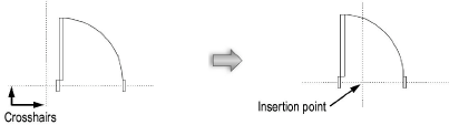
When editing components, make the symbol edits in the Attributes or Object Info palette. To edit the symbol insertion point, select all the components of the symbol, and relocate the components about the insertion point crosshairs. The intersection of the crosshairs gives the feedback segment Locus when encountered.
The other component of a hybrid symbol is not automatically adjusted to match changes made to the insertion point. It must be edited separately. Switch easily to the other component from the context menu.
After editing, click the Exit Symbol button (or select Modify > Exit Symbol) to update all instances of the symbol and return to the normal drawing mode.