 Inserting a Photometric Grid Inserting a Photometric Grid
 The photometric grid is a is a three-click rectangular object, and can be inserted in Center-line Placement mode or Edge Placement mode. The grid can be tilted, accounting for sloped or raked stages.

Placement Mode |
Description |
Center-line |
Click once, and then again, to define the length through the center of the grid. Click again to specify the grid width. |
Edge |
Click once, and then again, to define the length along the edge of the grid. Click again to specify the grid width. |

To insert a photometric grid:
Ensure that each lighting instrument contributing to the illumination is focused.
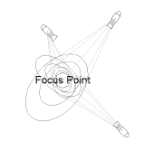
The light beams do not have to be drawn for calculations to be made.
Click the Photometric Grid tool from the Spotlight tool set, and then click a placement mode from the Tool bar.
Click in the drawing area to insert the photometric grid.
The first time you use the tool in a file, a properties dialog box opens. Set the default properties, and click OK. The properties can be edited from the Object Info palette.
Click to show/hide the parameters.
After placing the photometric grid, set the grid’s Z value from the Object Info palette; illumination values vary depending on the grid’s elevation.
~~~~~~~~~~~~~~~~~~~~~~~~~
![]()