 Creating Structural MembersCreating Structural Members
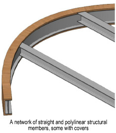
The Structural Member tool has the capability to insert straight and polylinear structural members composed of a variety of common materials and shapes, and to build networks of associated members. Structural members can be aligned with the layer plane or a working plane, as needed.
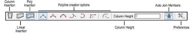
The following modes are available.
Mode |
Description |
|
Column Insertion |
Inserts a vertical member |
|
Linear Insertion |
Inserts a linear member |
|
Poly Insertion |
Draws a structural member using the selected polyline creation options and the current preference settings (see Structural Member Settings) |
|
Polyline creation options |
For Poly Insertion mode, selects the method for drawing the polyline upon which the object is based; see Creating Polylines |
|
Column Height |
For vertical members, enter the column height |
|
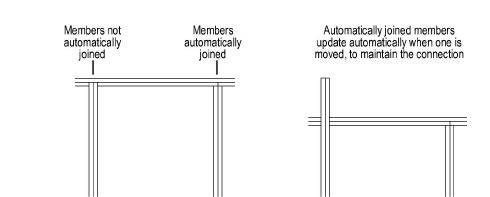
Auto Join Members |
When selected, automatically joins connected members and maintains the association between the member being moved and adjoining members; members can be joined to another member’s start or end point, centerline or edge. Associations are maintained for copied and duplicated objects, including objects moved to a different document. |
|
Preferences |
Opens the Structural Member Settings dialog box to set the default preferences for structural members |

To create a vertical structural member:
Click the Structural Member tool from the Building Shell tool set and then click Column Insertion mode from the Tool bar.
Click Preferences from the Tool bar to set the object defaults and click OK (see Structural Member Settings). Most of the properties can be edited later from the Object Info palette.
Enter the Column Height on the Tool bar.
If Auto Join Members mode is enabled, as you move the cursor over an existing structural member, the object is highlighted, indicating that it can be associated. Click to place the structural member; it is inserted by its base.

To create a linear structural member:
Click the Structural Member tool from the Building Shell tool set and then click Linear Insertion mode from the Tool bar.
Click Preferences from the Tool bar to set the object defaults and click OK (see Structural Member Settings). Most of the properties can be edited later from the Object Info palette.
If Auto Join Members mode is enabled, as you move the cursor over an existing structural member, the object is highlighted, indicating that it can be associated. Click to place the structural member’s start point, and click again to place the end point.

To create a structural member by drawing a polyline:
Click the Structural Member tool from the Building Shell tool set and then click Poly Insertion mode from the Tool bar.
For information on using the polyline creation options, see Creating Polylines.
Click Preferences from the Tool bar to set the object defaults and click OK (see Structural Member Settings). Most of the properties can be edited later from the Object Info palette.
If Auto Join Members mode is enabled, as you move the cursor over an existing structural member, the object is highlighted, indicating that it can be associated. Click to set the starting point of the structural member, and then click to set each polyline vertex. Double-click to finish creating the structural member.
~~~~~~~~~~~~~~~~~~~~~~~~~
![]()