 Framing a WallFraming a Wall
The Vectorworks Architect product creates a highly detailed estimate of the placement and number of studs needed to frame walls. In addition to showing stud placement in a framing diagram, the Wall Framer command also automatically generates frame elevation drawings and two different worksheets, Frame TakeOff and Frame Wall Info.
To use the wall framer:
Ensure that the walls have the desired height. If necessary, change the wall height.
Select AEC > Framing > Wall Framer.
If a framing model has not yet been created, the New Framing Model dialog box opens. Enter a name for the framing model design layer (up to eight characters).
Click Create.
The Wall Framing dialog box opens. Select the desired settings for the framing model.
Click to show/hide the parameters.
The framing diagram and the 3D model representations also include symbols and inserted items, such as doors and windows.
The Wall Class dialog box opens. Enter the framing parameters for each wall class.
Click to show/hide the parameters.
Click OK to return to the Wall Framing dialog box.
Click OK to create the framing model.
The program creates the estimated framing for the walls and any other output information requested.
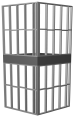
The 2D results display in Top/Plan view without a top plate. To view the results with a top plate, switch to another view such as Front, Back, Left, or Right.
To view the 3D results, switch to a view such as Left Isometric or Right Isometric.
The Framer TakeOff and Framer Wall Info worksheets, if created, display in the drawing area.
~~~~~~~~~~~~~~~~~~~~~~~~~
![]()