Open the file that contains the symbol definition to be edited.
Do one of the following:
● From the Resource Manager, right-click (Windows) or Ctrl-click (Mac) on the symbol definition, and select Edit from the context menu.
● For black or green symbols, right-click (Windows) or Ctrl-click (Mac) on a symbol instance in the drawing, and select Edit from the context menu. (You can also double-click on the symbol instance to edit it.)
Alternatively, select one of the other editing options from the context menu (for example, Edit 2D Component), to go directly into editing mode, and skip to step 4. Or, select Modify > Edit Symbol.
The Edit Symbol dialog box opens. Select editing options and click Edit.
Click to show/hide the parameters.
The Edit Symbol window opens, containing the symbol to be edited. A colored border around the drawing window indicates that you are in an editing mode. The Exit Symbol command becomes available from the Modify menu, and the Exit Symbol button is visible in the top right corner of the drawing window. See Object Editing Mode for more information.
To edit nested symbols, select Modify > Edit Symbol again.
Keep in mind that 2D objects that are part of a hybrid symbol must be in the screen plane to be visible in Top/Plan view; if they are not on the screen plane, they will be visible in 3D views. If you are pasting 2D layer plane objects from the clipboard while editing a symbol, an alert allows you to assign those objects to the screen plane. Normally, select Yes so that the top/plan graphics display correctly in Top/Plan view.
In addition, if you are editing a 2D-only symbol and adding 3D objects (including 2D layer plane objects), or editing a 3D-only symbol and adding screen plane objects, an alert informs you that you are creating a hybrid symbol. Portions of the symbol may not be visible in certain views. Similarly, if you are removing portions of a hybrid symbol during editing, you may be creating a 2D-only or 3D-only symbol which may not display as expected in certain views.
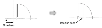
When editing components, make the object edits in the Attributes and/or Object Info palette. To edit the symbol insertion point, select all the components of the symbol, and relocate the components about the insertion point (origin) crosshairs. The intersection of the crosshairs gives the feedback segment Locus when encountered.
The other component of a hybrid symbol is not automatically adjusted to match changes made to the insertion point. It must be edited separately. Switch easily to the other component from the context menu.
A master snap point can be created when editing a symbol definition, setting the location by adding a 2D and/or 3D locus where priority snapping should occur, when enabled in Object Snapping. Place the locus with the appropriate component (2D locus for 2D component, 3D locus for 3D component). In the Object Info palette of the selected locus, select Master Snap Point. If the master snap point is in an obscure location and you want it to always display when the snap box is over the symbol instance, select Show Master Snap Point Outside Snap Box.
After editing, click the Exit Symbol button (or select Modify > Exit Symbol) to modify the symbol definition. The instances of black and green symbols are also updated.