By adding a 3D wall hole component to a symbol definition, the symbol has the ability to cut holes of any shape in a wall. The geometry drawn to define the shape of the 3D hole can consist of any solid shape or shapes. If a wall hole component is included in a symbol definition, any existing 3D loci in the 3D component of the symbol are ignored.
To add a 3D wall hole component to a symbol definition:
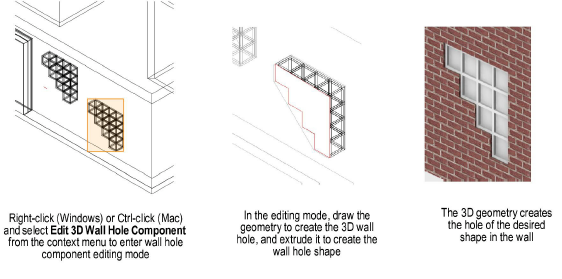
Select a black symbol instance from the drawing. Right-click (Windows) or Ctrl-click (Mac) on the symbol, and select Edit 3D Wall Hole Component from the context menu to enter wall hole component editing mode.
A colored border around the drawing window indicates that you are in an editing mode. The Exit Wall Hole Component command becomes available from the Modify menu, and the Exit Wall Hole Component button is visible in the top right corner of the drawing window.
Any solid shape can be drawn to define the hole shape. The geometry must intersect the wall.
Select the 2D Polygon tool or Polyline tool from the Basic palette and trace the symbol outline to define the hole shape. Select Model > Extrude to create a 3D wall hole shape. Alternatively, create 3D wall hole geometry directly using 3D modeling tools. The wall hole geometry has a red pen style; this can be changed from the Attributes palette if desired.
Other drawing objects display, and can be snapped to, while in the editing mode (the Vectorworks display preference Show other objects while in editing modes must be enabled). The symbol being edited is displayed with its pen style attributes, to distinguish it from the rest of drawing.
Click Exit Wall Hole Component to return to the design layer.
Since the wall hole component was added to the symbol definition, all instances of the symbol will cut holes in walls according to the geometry drawn.
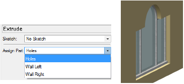
Special texture parts for wall hole components can be applied from the Object Info palette. See Applying a Texture to an Object. While editing the wall hole component, the Assign Part list on the Render tab of the Object Info palette lists three options for the different textures that can be applied to wall hole faces: Holes, Wall Left, and Wall Right.
Texture Part |
Result |
|
Holes |
Applies the texture specified for the wall’s “Holes” part to the wall faces created by the cutting object |
|
Wall Left |
Applies the texture specified for the wall’s “Left” part to the wall faces created by the cutting object |
|
Wall Right |
Applies the texture specified for the wall’s “Right” part to the wall faces created by the cutting object |
Each wall hole component can only have one texture part defined. Therefore, up to three different cutting objects would be necessary to apply three different texture parts to the wall hole faces.
~~~~~~~~~~~~~~~~~~~~~~~~~
![]()