 Rotating the PlanRotating the Plan
In a design layer, the view may need to be rotated to match a drawing angle. When the plan is rotated, the view switches to Rotated Top/Plan, and all existing layers are rotated together.
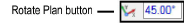
The View bar has a button for quick access to the Rotate Plan command.
To rotate the plan:
Select View > Rotate Plan, or click Rotate Plan from the View bar.
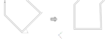
Click to indicate the center of plan rotation, and then click again to indicate the angle of plan rotation. The angle snaps to existing objects.
The temporary reference line indicates the line that will become horizontal after the operation. The temporary arrow within the arc indicates the direction of the rotation. The rotation is referenced to a horizontal line, unlike the Rotate tool.
The angle of plan rotation can also be specified from the floating data bar, or entered directly in the View bar. The drawing rotates around plan center (0, 0) when the angle is specified in the View bar.
All layers in the drawing rotate to match the specified angle. (If some layers were in a 3D view, they will lose this view since all layers in the drawing are set to Rotated Top/Plan; confirm that this is the desired action.) Symbols placed and objects drawn while in this view match the current rotation angle.
At the bottom left of the drawing window, the position of the X - Y axis indicator shows the drawing rotation angle and direction.
To disable the rotation animation, see Vectorworks Preferences: Interactive Tab.
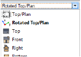
The View bar indicates that the drawing has been rotated; the icon next to the layers in the Layers list changes, and the Current View list displays Rotated Top/Plan. If you switch to another view and want to return to the rotated top/plan view, select Rotated Top/Plan from the Current View list on the View bar.
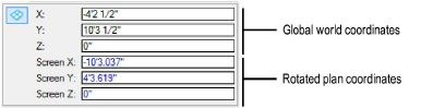
In addition, in a Rotated Top/Plan view, the rulers display in a blue color, and the Object Info palette for objects in rotated plan displays both global world coordinates and rotated plan coordinates (depending on the Object Info palette preference).
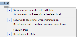
The display of the Object Info palette coordinates in rotated plan view is controlled by a preference, accessed from the Coordinate/IFC menu at the top right corner of the Object Info palette:
Click to show/hide the parameters.
Once the drawing has been rotated, a different rotation angle can be specified with Rotate Plan in the View bar.
The green reference line indicates the unrotated, horizontal direction. If the Rotate Plan command is selected again, match this reference line to un-rotate the view, returning to the world coordinate system. Alternatively, to un-rotate the view, select View > Standard Views > Top/Plan, select Top/Plan from the View bar, or enter an angle of 0 for Rotate Plan in the View bar.
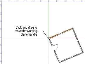
In rotated plan view, a working plane is automatically present, with its origin at the rotated plan pivot point and its X’ axis horizontal to the screen. Click the X’ or Y’ axis to drag the working plane to a new location. The X’ and Y’ coordinates adjust from this point and the local coordinates are reflected on the rulers.
An elevation view can be easily set based
on the working plane position. Click Working Plane
Views  from the
View bar, and then select a standard view such as Front. To return to
the rotated 2D view, select Rotated Top/Plan from the Current
View list on the View bar.
from the
View bar, and then select a standard view such as Front. To return to
the rotated 2D view, select Rotated Top/Plan from the Current
View list on the View bar.
The plan rotation can be saved as a view and restored later by selecting the view for display. Select Save View Orientation in the Save View dialog box to save the plan rotation (see Creating Saved Views).
Saved views with rotation information display with a rotated icon in the View column of the Organization dialog box. Sorting by the View column separates non-rotated views from the rotated views.
~~~~~~~~~~~~~~~~~~~~~~~~~
![]()