 Creating
the Rigging System
Creating
the Rigging System
Creating
the Rigging SystemThe Insert Truss tool places a section of truss on the drawing; depending on the resource selected, the truss may be straight, curved (or circular), or a corner element, and it may be horizontal or vertical. In Auto Connect mode, a truss connects to existing trusses, forming a truss system. When Auto Connect mode is disabled, the truss is not connected to an existing truss.
The following modes are available.
Mode |
Description |
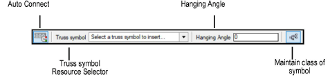
Auto Connect |
When enabled, connects the inserted truss to the current truss system with geometrical precision; also generates a preview of connected trusses that are being moved |
Truss symbol |
Select the truss to insert |
Hanging Angle |
Specifies the hanging angle from the X axis |
Maintain class of symbol |
Uses the class specification from the symbol definition; disable the mode to insert the truss into the active class instead |

To insert a truss symbol:
Click the Insert Truss tool from the Spotlight tool set. Click Truss symbol on the Tool bar. From the Resource Selector, double-click a resource to activate it.
If a symbol is not selected, the Select Symbol dialog box opens automatically to select one.
Alternatively, from the Resource Manager, either double-click the truss symbol to insert or right-click on the truss symbol and select Make Active from the context menu, and then select the Insert Truss tool. The Insert Truss tool is automatically selected.
If a truss symbol is accidentally inserted by the Symbol Insertion tool, the truss functionality will not be present. When correctly inserted, the Object Info palette displays “Truss” for the selected truss.
If the selected truss has insufficient information for proper calculations, the Truss Properties dialog box opens automatically, to enter required information; see Creating a Custom Truss Symbol.
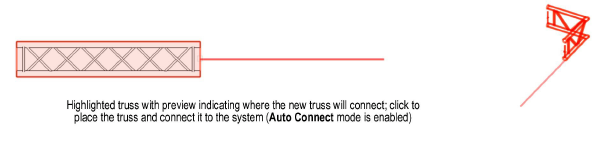
If this is the first truss placed, click to place the object in the drawing, and click again to set the orientation. If connecting to an existing truss system, enable Auto Connect mode. When adding a truss to an existing system, a valid existing component to connect to is highlighted, indicating that if placed there, the new component will connect to the system (the Connectable with parameter determines whether structural elements can connect); see Concept: Creating a Connected Rigging System. Move the mouse to hover over the connection; depending on the type of truss being attached and the view, various options are previewed for connecting the truss. For example, connecting a three way corner truss will have different insertion options available from connecting a four way truss, and Top/Plan view will provide different previews from 3D insertion. When the desired location and orientation is highlighted, click to place the truss.
If no highlighting occurs with Auto Connect mode enabled, the trusses are not connectable.
The truss properties can be edited from the Object Info palette.
► Click to show/hide the parameters.
~~~~~~~~~~~~~~~~~~~~~~~~~