 Creating a Graticule
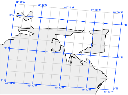
Creating a GraticuleUse the Graticule tool to place a reference grid object over the drawing. Unlike a grid that is based on X and Y coordinates, the graticule lines are based on longitude and latitude lines that are inferred from the layer projection.
Mode |
Description |
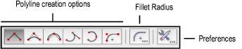
Polyline creation options |
Selects the method for drawing the polyline that will bound the graticule object; see Creating Polylines. |
Fillet Radius |
If the Arc Vertex mode is selected, specifies the fillet radius to use |
Preferences |
Sets the default parameters to be used for the tool |

To create a graticule:
From the Site Planning tool set, select the Graticule tool.
From the Tool bar, click the Preferences button.
The Graticule Properties dialog box opens.
► Click to show/hide the parameters.
Click OK to save the default graticule settings.
From the Tool bar, select the type of polyline to use as the boundary for the graticule.
Click the drawing to create the polyline boundary in the approximate location of the latitude and longitude lines you specified. Make the polyline larger than the graticule will be, so the graticule will not be cut by the polyline. When you complete the polyline, a graticule object is created over the specified location.
The software automatically calculates the minimum and maximum values for the latitude and longitude using the geometry and location of the defined polyline. These values can be edited later from the Object Info palette.
~~~~~~~~~~~~~~~~~~~~~~~~~