 Creating Objects from Shapes
 Creating Objects from Shapes
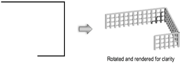
The Create Objects from Shapes command uses an existing polyline or shape as the path for creating a variety of objects, as listed in the following table.
Object |
Product |
ceiling grid |
Architect |
detail-callout marker |
Architect, Landmark, Spotlight |
guardrail |
Architect, Landmark |
hardscape object |
Landmark |
irrigation design zone |
Landmark |
irrigation drip outlet |
Landmark |
irrigation hydrozone |
Landmark |
irrigation pipe |
Landmark |
landscape area |
Landmark |
landscape wall |
Landmark |
lighting pipe |
Spotlight |
linear material detail |
Architect, Landmark |
massing model |
Architect, Landmark |
parking along path |
Landmark |
parking area |
Landmark |
piping run |
Architect |
plant |
Landmark |
property line |
Architect, Landmark |
railing/fence |
Architect, Landmark |
repetitive unit detail |
Architect, Landmark |
revision cloud |
Architect, Landmark, Spotlight |
roadway |
Architect, Landmark |
roadway (custom curb) |
Architect, Landmark |
roadway (NURBS) |
Architect, Landmark |
roadway (poly) |
Architect, Landmark |
seating layout |
Architect, Spotlight |
site modifier |
Architect, Landmark |
slab |
Architect, Landmark, Spotlight |
soft goods |
Spotlight |
space |
Architect, Landmark, Spotlight |
stipple object |
Architect, Landmark, Spotlight |
wall |
Architect, Landmark, Spotlight |
In addition to these standard objects, the Create Objects from Shapes command supports custom path objects (custom path plug-in objects with a .vso extension). For details, see Creating Custom Path Objects.
Walls created with the Create Objects from Shapes command use the current settings made active by the Wall tool (Vectorworks Design Series required), and slabs use the current Slab tool settings (Vectorworks Architect required).
To create a specific site modifier such as a pad or pad with retaining edge, select Site Modifiers (Vectorworks Architect or Landmark required) and then specify the type of site modifier from the Config list of the Object Properties dialog box.
In the Vectorworks Fundamentals workspace, walls can be created from polygons using the Create Walls from Polygon command (see Creating Walls from a Polygon).
To create an object from a shape:
Draw a polyline or select an existing shape such as a line, rectangle, oval, polygon, arc/circle, rounded rectangle, polyline, or 3D polygon representing the path for creating the object.
With the item selected, select the Create Objects from Shapes command from the appropriate menu:
● Architect workspace: AEC > Create Objects from Shapes
● Landmark workspace: Landmark > Create Objects from Shapes
● Spotlight workspace: Modify > Create Objects from Shapes
Alternatively, right-click and select Create Objects from Shapes from the context menu.
The Create Objects from Shapes dialog box opens.
Select the type of object and the creation parameters.
► Click to show/hide the parameters.
Click OK. If Show Properties Dialog is selected, the object properties dialog box for the specified object type opens. Enter the appropriate parameters, and then click OK.
If you are creating guardrails and Continuous Spacing is selected in the Create Objects from Shapes dialog box, enter the distance between the first upright and the start of the shape in the 1st Upright Spacing field of the object properties dialog box. If Continuous Spacing is not selected, this value is applied to the first upright at the beginning of each segment of the shape. Also enter the spacing to maintain between uprights in the Upright Spacing field of the object properties dialog box.
The object is created from the shape and its parameters can be edited from the Object Info palette.

~~~~~~~~~~~~~~~~~~~~~~~~~