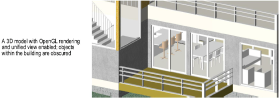
The Clip Cube command allows you to temporarily clip away portions of a 3D model to see and work inside of the model. Only objects inside the cube are visible and snappable. Less clutter makes it easier to locate snap points or to view a specific region of interest in a large 3D model.
The clip cube feature only works in Wireframe and OpenGL rendering modes. Select objects in the area to view, and then select the Clip Cube command to create a cube that bounds those objects. Once the cube is created, use the Selection tool to push or pull the cube faces to adjust the size. Use the cube’s editing frame to rotate it or drag it to another location.
To align the working plane with the highlighted face of a clip cube, right-click a highlighted horizontal or vertical face of the clip cube and select Set Working Plane from the context menu.
To use the clip cube feature:
In a 3D view, select the objects to be visible inside the cube. (If no objects are selected, the cube will bound all currently visible objects.)
Set the rendering mode to Wireframe or OpenGL.
Select View > Clip Cube.
Alternatively, add the Clip Cube shortcut button to the Tool bar; see Setting Quick Preferences.
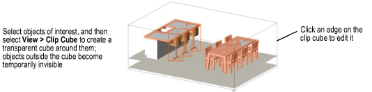
The view is clipped to show only the area of the model that contains the selected objects; the objects are surrounded by a transparent cube. By default, cross-section areas of solid objects are displayed in red, along the plane where the clip cube cuts.
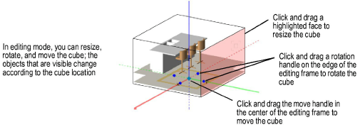
To modify the clip cube, click an edge on the cube with the Selection tool. An editing frame with X, Y, and Z axes displays on its bottom face. During editing, the view changes to show the objects within the cube at any given time.
Action |
Description |
|
To adjust the cube dimensions |
Similar to the Push/Pull tool, a face of the cube becomes highlighted when the cursor is over it. Click a highlighted face and drag it; click again to set to the new location. |
|
To rotate the cube |
Click one of the four rotation handles on the edges of the editing frame on the bottom face of the clip cube. Drag to rotate the cube, and then click to set the new location. |
|
To move the cube |
Click the move handle in the center of the editing frame. Drag to move the cube, and then click to set the new location. |
Edit the objects within the clip cube. Keep in mind the following:
● If you edit a symbol, the clip cube will be reset to the symbol boundary; when you exit the symbol editing mode, the cube returns to its original boundary.
● While the clip cube feature is enabled, you can create a different cube on each design layer. However, if the unified view feature is enabled, only one clip cube can be created.
To save the current clip cube view for later use, select View > Save View, and select the option to Save View Orientation (see Creating Saved Views).
Select the Clip Cube command again to disable the clip cube and return to a full model view on all design layers.
(A check mark next to the Clip Cube command indicates that the feature is activated.)
If you hold down the Ctrl key (Windows) or Command key (Mac) the next time you select the Clip Cube command, the last clip cube you had on this design layer is restored.
 Creating a Section Viewport from a Clip Cube
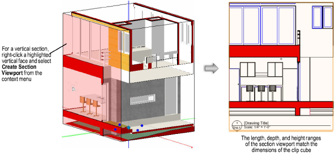
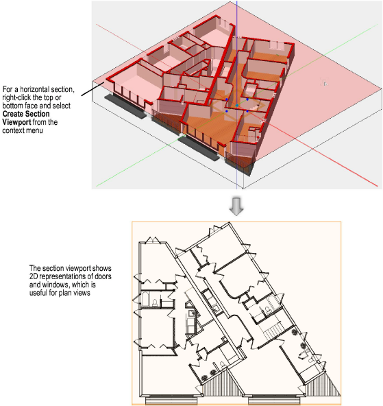
After you create a clip cube, select the Selection tool, and then right-click a highlighted horizontal or vertical face of the clip cube.
Select Create Section Viewport from the context menu. The Create Section Viewport dialog box opens.
Create the viewport either on a sheet layer or design layer, as described in the following topics:
● Creating a Section Viewport on a Sheet Layer
● Creating a Section Viewport on a Design Layer
By default, the cross section areas are shown with red fill. These areas are in the Section Style class, if you want to change the fill color.
Alternatively, display the cross section areas with the original objects and attributes. From the Object Info palette, access the viewport’s Advanced Properties. From the Attributes tab, select Separate Cross Sections and Use Attributes of Original Objects.
For details about editing other properties of the viewport, see Advanced Section Viewport Properties.
► Click here for a video tip about this topic (internet access required).
~~~~~~~~~~~~~~~~~~~~~~~~~