If you are creating 2D components for a plug-in object style or plug-in object instance, right-click on the resource or object and select 2D Component Options from the context menu. If you are creating 2D components for a symbol definition, skip to step 4.
The Plug-in Style 2D Component Options dialog box or Plug-in 2D Component Options dialog box opens.
If you are creating components for the plug-in object style, set whether the parameters will be defined by style or by instance (see Concept: Plug-in Object Styles). If you are creating components for an instance, check the by style/instance settings to confirm that you can create components for this instance; however, the by style/instance setting can only be established from the Plug-in Style 2D Component Options dialog box.
![]() Click
to show/hide the parameters.
Click
to show/hide the parameters.
Click OK.
Do one of the following:
● To edit a symbol definition or plug-in object style, locate the resource in the Resource Manager, and then right-click on it and the select Edit 2D Components from the context menu.
● To edit a plug-in object instance in the drawing, right click on the object and then select Edit 2D Components from the context menu.
You can also right-click on a symbol instance in the drawing; however, this method edits the symbol definition. A single symbol instance cannot be edited.
The object opens in Object Editing Mode, with the working plane set to Screen Plane.
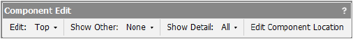
When editing the components of symbol definitions and plug-in objects, an additional Component Edit palette displays, and additional parameters are available in the Object Info palette.
![]() Click
to show/hide the parameters.
Click
to show/hide the parameters.
In the Component Edit palette, select the component to Edit.
For objects with opposite sides that are mirror images, such as the left and right side of a toilet fixture, there is no need to create a 2D component for both views. Select Mirror opposite view graphics for empty 2D Components in the Create Symbol dialog box or Symbol Options dialog box for symbol definitions (see Creating Symbol Definitions), or in the Plug-in Style 2D Component Options or Plug-in 2D Component Options dialog box for plug-in styles or instances (see step 2).
Select the desired Show Other view and Show Detail level to use as visual aids.
Select Generate 2D from 3D Component from the context menu. Select the line rendering style for the 2D component from the Generate 2D Graphics from 3D Component dialog box.
The 2D component for the selected view is created as a group and correctly aligned with the other components. You can edit the group or ungroup the component for editing.
Alternatively, you can individually draw the lines and shapes on the screen plane to create the desired 2D component using the Vectorworks tools and commands. Be careful to align the 2D components correctly with the 3D components and other component views for correct display in a viewport.
Edit the component as needed. In addition to the object editing capabilities available for any object in Vectorworks, it is possible to relocate the component location or display different detail levels, as needed for correct presentation.