 Creating design
zones
 Creating design
zones
Creating design
zonesMode |
Tool |
Tool set |
Modes for the Polyline tool |
Design Zone
|
Irrigation |
Once outlets (and drip outlets) have been placed on the drawing, it can be useful to balance the required water usage of the outlets by placing them into design zones, before adding the pipes and valves to the outlets. Design zones help you know how to group outlets into zones so that the requirements of the zones can be met by the water pressure and flow available from a Point of Connection (POC) water source.
Design zones also analyze the spray/arc patterns and can help you estimate the coverage overlap of outlets, as well as determine whether some areas do not have sufficient coverage.
The following modes are available.

Mode |
Description |
Outlet Type list |
Select the type of outlet to be considered for the design zone; if there are multiple types, choose Select Multiple |
Polyline Creation Options |
Selects the method for drawing the polyline upon which the object is based; see Creating polylines |
Preferences |
Sets the default preferences for the design zone object |
To create a design zone:
1. Before creating the design zone, place outlets and, optionally, a POC on the drawing, in the expected configuration.
2. Click the tool and select the Outlet Type from the Tool bar.
Choose Select Multiple if the design zone should consider various types of outlets. The Select Outlet Types dialog box opens; place a check mark in the Include column for outlets to be considered by the design zone. When the zone will contain multiple outlet types, <Multiple Selection> displays in the Outlet Type list.
3. Click the appropriate mode from the Tool bar to specify the creation method of the design zone polyline.
Alternatively, create a polyline and then select the Create Objects from Shapes command (see Creating objects from shapes).
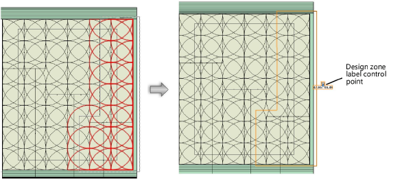
4. Click to start drawing the design zone. As you draw the design zone polyline, outlets to be included in the design zone are highlighted. Draw the design zone polyline, clicking at each vertex. Click at the start point, or double-click, to finish drawing the design zone.

The Design Information section, available from the Object Info palette, provides analysis data to help determine whether the outlets in the design zone are efficiently using the water supplied by the POC. Change the outlet types considered by the design zone calculations by clicking Reassign Outlets.
After creation, the design zone shape can be edited with the Reshape tool. The design zone properties can be edited from the Object Info palette.
 Click
to show/hide the parameters.
~~~~~~~~~~~~~~~~~~~~~~~~~