Tool
Tool set
Shortcut
Light

Visualization
Shift+Z
Tool |
Tool set |
Shortcut |
Light
|
Visualization |
Shift+Z |
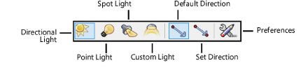
The Light tool places light sources in the drawing. Select the type of light and specify the light preferences.
Mode |
Description |
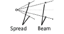
Directional Light |
Projects light with parallel rays, like the sun |
Point Light
|
Radiates light in all directions, like a bare light bulb |
Spot Light
|
Projects light in a specific direction, aimed at a specific object, like a flashlight or conventional spotlight |
Custom Light
|
Defines the source’s emission distribution by a standard intensity distribution profile for accurate physical lighting |
Default Direction |
For directional lights, click to specify the light position |
Set Direction |
For directional lights, click to set the light direction, and then click to specify the light position |
Preferences |
Sets the preferred light parameters |
Adding a visible light source to a drawing hides the default lighting scheme that is automatically present for basic rendering purposes. The design layer containing the light source must contain 3D geometry upon which to project the light, and the 3D objects must not have a perfectly black fill (which absorbs all light).
Other methods of adding light include the linear light and the area light; see Inserting an area or linear light , and in the Vectorworks Design Series, the Heliodon tool (see Solar studies).
To add a light source:
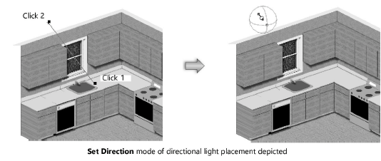
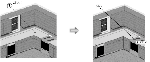
1. Click the tool and select the type of light source to insert (Directional Light, Point Light, Spot Light, or Custom Light). If inserting a directional light, click the light placement mode (Default Direction or Set Direction).
2. Click Preferences to specify the light source preferences for this session.
For custom lights, the Custom Light Data dialog box opens. For other light types, skip to step 5.
3. Click Load Distribution and specify the location of the custom light distribution file, and then specify any additional custom light parameters.
![]() Click
to show/hide the parameters.
Click
to show/hide the parameters.
4. Click OK.
The Light Preferences dialog box opens.
5. Set the parameters.
![]() Click
to show/hide the parameters.
Click
to show/hide the parameters.
6. Click Directional Light Specs, Spot Light Specs, Point Light Specs, or Custom Light Specs for the selected light source type, to specify additional parameters.
![]() Click
to show/hide the parameters.
Click
to show/hide the parameters.
7. Click OK to return to the Light Preferences dialog box. Click OK to return to the drawing.
8. Click to place a light object with the parameters specified in the Light Preferences dialog box.
If placing a directional light, click to specify the light position in Default Direction mode. In Set Direction mode, click once to specify the light target or direction, and then click a second time to specify the light position.
If placing a spot light, click to place the light, and then drag to specify the light direction and target. The spot light can be aimed at any object. Click again to set the spot light. Use the Look To Height parameter on the Object Info palette to adjust the target Z height precisely.
The spot light target handle and projection line only display when the spot light is selected. Use the Selection tool to move the light. The target handle aims the spot light and can be adjusted with the Selection tool once the spot light has been created. Use the Reshape tool to move the target handle constrained about an axis selected in the Tool bar.
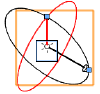
The custom light object is represented by a pair of perpendicular arrow-head vectors and two perpendicular circles. The black vector points to the target location; its axis line (the light axis) connects the light source location to the target. The red vector starts at the light source location, pointing to a reference point on the “equator” of the polar intensity distribution. Also known as the “zero angle line,” it represents the origin for measuring the intensity on the light curve.
The two vectors form the black circle, and the red circle is perpendicular to it. The black circle represents the original plane where the light curves are located. The red circle constrains the movement of the zero angle line.
~~~~~~~~~~~~~~~~~~~~~~~~~