Shaft
segment propertiesShaft
segment properties
Shaft
segment propertiesShaft
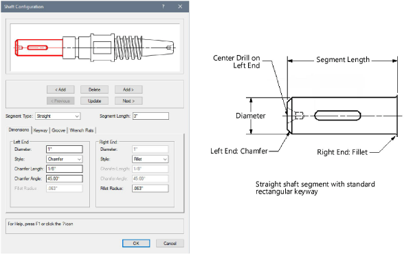
segment propertiesTo add, delete, or modify component segments to construct the desired shaft object:
1. Select a shaft in the drawing file and click the Configuration button from the Object Info palette.
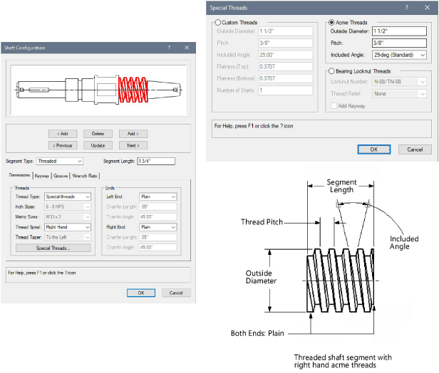
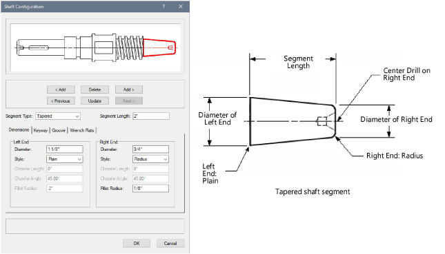
2.While the currently selected segment is highlighted, specify the shaft segment parameters on each tab to define the shaft. Click the Update button to dynamically change the preview when changes are made.
3.Click the Dimensions tab to specify the configuration of the shaft segment.
![]() Click
to show/hide the parameters.
Click
to show/hide the parameters.
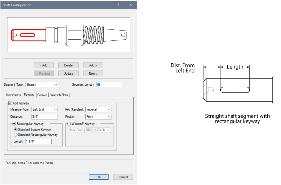
4.Click the Keyway tab to specify the configuration of the shaft segment keyway (straight Segment Type only).
![]() Click
to show/hide the parameters.
Click
to show/hide the parameters.
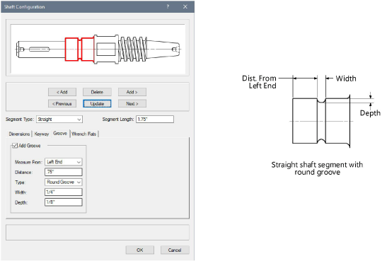
5.Click the Groove tab to specify the configuration of the shaft segment groove (straight Segment Type only).
![]() Click
to show/hide the parameters.
Click
to show/hide the parameters.
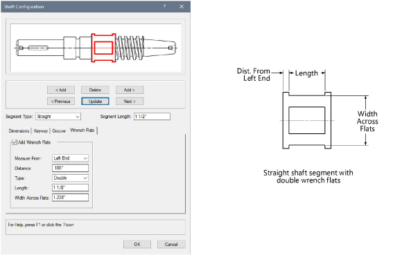
6.Click the Wrench Flats tab to specify the configuration of the shaft segment wrench flats (straight Segment Type only).
![]() Click
to show/hide the parameters.
Click
to show/hide the parameters.
7.To edit parameters, click Configuration from the Object Info palette, double-click the shaft, or select Edit from the context menu to open the Shaft dialog box. The following additional parameters can be modified directly from the Object info palette.
![]() Click
to show/hide the parameters.
Click
to show/hide the parameters.
~~~~~~~~~~~~~~~~~~~~~~~~~