 Creating a bridle
assembly diagramCreating a bridle
assembly diagram
Creating a bridle
assembly diagramCreating a bridle
assembly diagramCommand |
Path |
Create Bridle Assembly Diagrams |
Spotlight > Rigging |
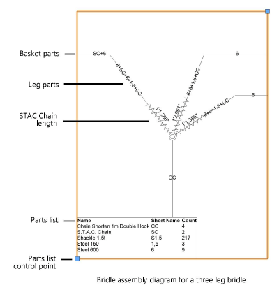
Create simple assembly diagrams for selected bridles in the drawing. Each diagram includes a schematic drawing with labeled parts and an optional parts list. The diagrams can be placed on a sheet layer or design layer, and arranged in one or more columns.
To create a bridle assembly diagram:
1. Select one or more bridle objects, and select the command.
The Create Bridle Assembly Diagram dialog box opens.
![]() Click
to show/hide the parameters.
Click
to show/hide the parameters.
2.Set the parameters for the bridle assembly diagram.
A diagram is created for each selected bridle. If multiple diagrams are created, they are arranged in the specified Number of columns.
To print one diagram per sheet, place the bridle assembly diagrams in one column on a sheet layer. Set the diagram size to match the Printable Area dimensions specified in Page setup. From the Page Setup dialog box, set the Vertical page count to match the number of selected bridles.
3.Click and drag the bridle assembly diagram to reposition it. To reposition the parts list independently from the assembly drawing, click the control point at the bottom of the parts list, and click again at the desired location.
4.Use the Text menu commands to edit the font, size, and style of the text in the entire assembly diagram (see Formatting text), or apply a text style (see Using text styles).
The parameters can be edited from the Object Info palette.
![]() Click
to show/hide the parameters.
Click
to show/hide the parameters.
~~~~~~~~~~~~~~~~~~~~~~~~~