 Multi-cell lighting device specificationsMulti-cell lighting device specifications
Multi-cells represent a special case of the lighting device object. Each symbol drawn should represent a single element of the multi-cell lighting device. A lighting device that is at the end of the multi-cell strip should look different from the lighting devices that are in the center. Place the number of symbols required to create the multi-cell device. For example, place four symbols (two ends and two middle) to create a four-cell cyc unit.
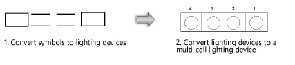
The multi-cell symbol must consist only of other symbols to be properly inserted as a multi-cell lighting device. Otherwise, the Lighting Device tool treats it as a single-cell device.
Attach the Light Info record to the individual lighting devices within the multi-cell unit by the same method as for an individual lighting device; see Attaching the Light Info record and Light Info M record. Then attach a Light Info record to the container multi-cell symbol, but with no data specified in the record.
Multi-cell symbols can support multiple light sources. Place a 3D locus at the site of each light emitter. Attach the Parts record to each locus and assign a Light Emitter value indicating which cell will control the emitter’s light color; see Attaching the Parts record. When the lighting device is rendered, each locus is converted to a light source. All loci with the same Light Emitter value have the same light source properties.
Adding many emitters can significantly slow the rendering.
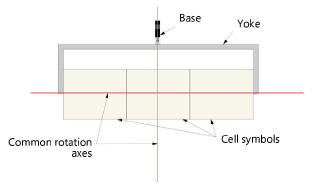
The multi-cell lighting device focuses in 3D in the same way as individual lighting devices; see Lighting device specifications. The yoke is created from portions of the individual lighting device symbols. The 3D locus, placed within the container multi-cell symbol, is used as a common rotation axis for the entire multi-cell unit.
~~~~~~~~~~~~~~~~~~~~~~~~~