 Lighting device specificationsLighting device specifications
Special rules apply when creating a symbol to be converted to a lighting device; see Creating symbol definitions.
Symbols should be hybrid (2D/3D) so they display properly in both 2D and 3D views. At a minimum, the symbol must contain a 2D component, which must be a screen plane representation and not a 2D planar object.
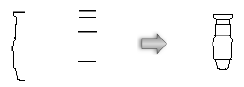
Create the 2D view of the symbol using as few polygons and lines as possible. Try using a single polyline rather than individual line segments. All lighting devices should be drawn with the front of the device (the end which emits light) oriented towards the top of the drawing. The symbol below was created from these few constituent parts:
The line weight of the symbol is also a consideration; the devices need to stand out when printed. The outer perimeter of the symbol should have a line weight of at least 0.25 mm. Interior details should use a lighter line weight, such as 0.13 mm or 0.18 mm.
The 2D representation should have a solid fill so that it obscures information under the symbol. The size of the lighting device should be accurate based on the real device it represents. While drawing the lighting device, keep the level of detail as minimal as possible. The goal is to be able to distinguish lighting devices from one another, not to create a detailed plan view of each device.
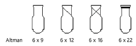
For lighting devices with multiple configurations, it is acceptable to use simple graphical differences to distinguish among the models. For example, use the following variations for the different versions of a symbol:
A lighting device symbol can support multiple light sources; see Multi-cell lighting device specifications for more information. When creating multi-cell symbols, place a 3D locus at the site of each light emitter. Attach the Parts record to indicate which emitters should work together across multiple cells; see Attaching the Parts record.
Adding many emitters can significantly slow the rendering.
One or more accessories can be added directly to the lighting device symbol. For example, a clamp can be imported from the Vectorworks symbol library and embedded in your lighting symbol. This allows you to insert lighting devices with the desired accessories already attached. By default, the accessory insertion point is the top-center of the lighting device’s bounding box in 2D views and the back-center of the bounding cube in 3D views. You can change this default positioning with the use of a layout symbol; see Defining the accessory’s default position. By default, the accessory attaches to the lighting device body, so the accessory moves and rotates with the device as you position and focus it. If the accessory is a clamp, attach the Parts record and specify the Base part, so the lighting device can be properly offset when inserted; see Attaching the Parts record.
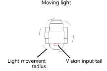
For moving lights, draw a circle around the lighting device to denote the light movement radius. Use a dashed line type. Place the circle’s center point at the device insertion point, and draw the radius to the correct length for the light to sweep.
 .
.
If you’ll be exporting to the Vision program, add an input tail where the lighting device will receive power. Draw a rectangle 100 mm long and 50 mm wide to represent the Vision input tail. This connection point can help you orient the symbol correctly in Vision.
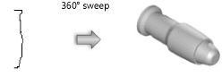
The 3D portion of the lighting device should be drawn as if it is hung straight down (along the Z-axis) with the yoke oriented along the Y-axis. The top of the lighting device should point towards the top of the drawing. To generate a reasonable 3D device body, sweep the 2D portion of the symbol. The segment angle of the sweep should be between 20° and 40°. See Sweeping objects for more information.
Keep the 3D symbol simple. It should be solid. The symbol should be accurately sized, but without minute details like handles, grommets, fins, louvers, cords, and knobs. These items can add significantly to the rendering time required, and are not necessary to distinguish among lighting devices.
The 3D symbol should consist of five main parts: the body, lens, 3D locus point, yoke, and base. Only one of each part can exist in the symbol. However, a part may contain multiple sub-parts grouped together; see Attaching the Parts record for details. Several additional parts are optional.
● The body is the part of the lighting device where light is emitted.
● Optionally, create multiple light emitters by placing a 3D locus for each emitter within the body.
● Add a lens to the body. This can be a simple extruded circle of 1 mm protruding from the body. The fill should be RGB (204, 254, 255).
● Place a 3D locus within the body at the rotation point for the yoke. The X,Y coordinates must be 0,0.
● The yoke connects the body to the base.
● The base consists of either a base motor unit for moving lights or a clamp or other hanging device for conventional lights.
● Optionally, add a clamp symbol to the base. See Attaching the Light Info record to an accessory symbol for details.
● Optionally, add a 3D input tail for exporting to the Vision program. The tail should be an extruded rectangle 100 mm long, 50 mm wide, and 50 mm high.
All the parts should be aligned as shown; the yoke rotates about the Z-axis, and the body rotates at the height of the locus point.
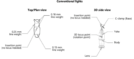
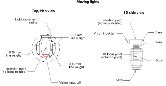
The symbol insertion point represents the lighting device’s hanging point.
Align the 2D and 3D versions of the symbol so their insertion points line up. Then, create the symbol as described in Creating symbol definitions.
When a base accessory, such as a clamp, is attached to a lighting device, the insertion point of the lighting device automatically adjusts to match the accessory’s origin point. If there are multiple base accessories, the origin point of the first accessory in the stacking order is used. When the base accessory is removed, the lighting device assumes its original insertion point.
The base accessory must have the Parts record attached to specify the accessory as a Base part.
The Parts record is required for proper 3D rotation of the lighting device. Attach the Parts record to each of the five main device parts: base, yoke, body, lens, and 3D locus point (rotation point). If adding base accessories such as clamps or adding 3D loci for light emitters, attach the Parts record to these objects as well. (See Attaching record formats to symbols, objects, and materials for more information.) Some of these parts need to be grouped, with a record applied to the group.
To attach the Parts record:
1. From the Resource Manager, locate a Parts record from one of the lighting device library files included with the Spotlight program, and drag it to the active file. Alternatively, right-click on the record, and select Import from the context menu.
2.Select the new symbol, and select Modify > Edit Symbol.
3.In the Edit Symbol window, group any sub-parts that should rotate together as one main part. For example, if a Vision input tail is located on the base of the lighting device, group the input tail with the base geometry to form the base part.
Do not group the lens and body at this time. Do not group an accessory with any other part.
4.Select the base, yoke, 3D locus point (rotation point), or accessory.
5.For each of these parts individually, do the following:
● Click the Data tab on the Object Info palette. Click Attach Record to open the Resource Selector, and double-click the Parts record to attach it.
● Select the appropriate part from the record fields (Base, Yoke, or Point).
Clamps should be designated as Base parts.
6.In the Edit Symbol window, select the lens.
7.Repeat step 5 for the lens (select Lens from the record fields).
8.In the Edit Symbol window, group the lens with the body geometry to form the body part.
9.With the grouped body part selected, repeat step 5 for the body (select Body from the record fields).
10.For multi-cell symbols that contain 3D loci for light emitters, select each locus point individually, and do the following:
● Click the Data tab on the Object Info palette. Click Attach Record to open the Resource Selector, and double-click the Parts record to attach it.
● Assign a Light Emitter value indicating which cell in the multi-cell unit will control the emitter’s light color. Enter the same value for emitters that will work together across multiple cells. For example, enter 1 for each emitter that should use the color specified for cell #1.
11.Click Exit Symbol at the upper right corner of the window to return to the drawing.
The bounds of the lighting device symbol are calculated in the device’s home position, with no rotation, and include all previously added accessories.
Attach the Light Info record to the lighting device symbol, with field names that match the names of the fields in the lighting device object. This record format is required. Not all the fields are required, but the desired fields for the lighting device object to read should be included. Filling out as much of the manufacturer information as possible is recommended.
The Light Info M record provides metric measurements of the weight and frame size of the lighting device object. This record format is additionally needed for lighting devices that could be used in both imperial and metric drawings.
To attach the light info record:
1. From the Resource Manager, locate the Light Info Record and Light Info Record M from one of the lighting device library files included with the Spotlight program, and drag them to the active file. Alternatively, right-click on the records, and select Import from the context menu.
2.Select the new symbol, and select Modify > Edit Symbol.
3.In the Edit Symbol window, click an empty location so that nothing is selected.
4.Click the Data tab on the Object Info palette. Click Attach Record to open the Resource Selector, and double-click the Light Info Record to attach it to the symbol. Enter its record information.
The Candlepower, Beam Angle, and Field Angle parameters affect the photometric grid and photometer object calculations. The Beam Angle and Field Angle parameters affect the Draw Beam feature.
Normally, do not include text labels with the lighting device, as these are handled by the lighting device object. An exception can be made to distinguish different models or lamps of a lighting device. For example, create three versions of a single PAR64 symbol by adding MFL, WFL, and NSP text blocks.
Symbols should be named with the model name of the lighting device.
5.Repeat step 4 to attach and edit the Light Info Record M.
6.Turn the lighting device’s light on in the Visualization palette to include a spot light as part of the lighting device. While editing the symbol, the spot light can be added, and accurate lighting information specified with the parameters in Use Emitter. See Adding light sources for information on adding a spot light and setting accurate lighting parameters.
7.Click Exit Symbol at the upper right corner of the window to return to the drawing.
As an alternative to the process of manually editing the symbol definition to attach the Light Info (and/or Light Info M) record, use the Lighting Symbol Maintenance command as described in Lighting symbol maintenance . Add the symbol by clicking New, and the Light Info record is automatically attached to it. Once in the maintenance list, the record data can be easily edited.
~~~~~~~~~~~~~~~~~~~~~~~~~