
Click here for a video tip about this topic (internet access required).
Many kinds of solid objects maintain a nested history of the manipulations conducted to shape them; prior steps can be accessed and edited using Object editing mode.
While many kinds of solid objects maintain a history that can be edited, generic solids do not. The use of a handful of tools—the Deform tool, Taper Face tool, and some modes of the Push/Pull tool—automatically results in a generic solid object. If you realize your solid operation created a generic solid and lost the object history, you can use the Undo command to step backward and regain the history. Conduct necessary edits before continuing with the operation that erases the history.
To edit an eligible solid object, you can either directly select a specific feature that helped to give the object its shape, such as a chamfer or an extrude, or you can enter the overall solid history of the object, to switch among and edit the multiple features used to create the object all in the same object editing session.
|
|
Click here for a video tip about this topic (internet access required). |
To edit an individual feature of a solid object:
1. Right-click on the solid object and select Edit Features from the context menu.
Alternatively, double-click on the solid object, and click Edit features from the Select Edit Method dialog box.
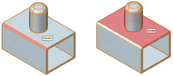
As you move the cursor over the selected object, faces are highlighted, and a screen tip indicates which feature of the solid will be edited if the highlighted face is selected.
2.Do one of the following:
● Click on a highlighted face to enter object editing mode with the feature selected to edit. Skip to step 4.
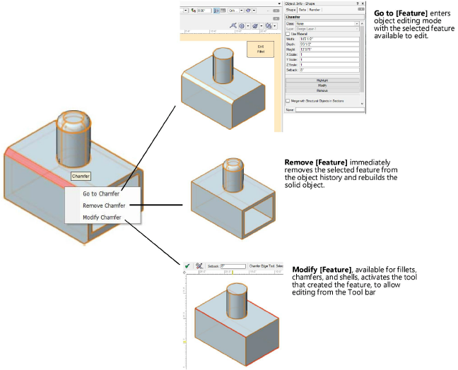
● Right-click on a highlighted face to access a context menu with additional options.
3.If you right-click on the face, a feature-specific context menu displays; select the desired command.
Some solid objects that depend on edge- and face-specific operation, including fillet, chamfer, and shell objects, offer additional editing capabilities; see Modifying a fillet, chamfer, or shell object.
4.If you are in object editing mode, once the edits are completed, click Exit [object] as many times as needed to exit object editing mode, or select Modify > Top Level to reapply all the features and return to the object in its final form.
Many kinds of solid objects maintain a nested history of the series of operations that shape them; prior steps can be accessed and edited, and the resulting solid object is rebuilt.
To edit multiple nested features within a solid object:
1. Right-click on the solid object and select Edit Solid from the context menu to enter object editing mode.
Alternatively, double-click on the solid object, and click Edit solid from the Select Edit Method dialog box.
2.Select the command again to step farther back into the object’s history until you reach the step you need to edit.
The Object Info palette indicates which nested object can be edited at each level.
3.Edit the nested objects as necessary to fine-tune the solid object’s shape. Use the Edit Solid command or Exit [object] as needed to access different nested features to edit.
4.Once the edits are completed, click Exit [object] as many times as needed to exit object editing mode, or select Modify > Top Level to reapply all the features and return to the object in its final form.
Some solid objects that depend on edge- and face-specific operation, including fillet, chamfer, and shell objects, offer additional editing capabilities; see Modifying a fillet, chamfer, or shell object.
A solid object can be created and edited using the following sequence of steps:
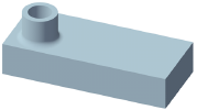
1. Use the Add Solids command to combine two overlapping solid objects (in this case a rectangular extrude and a taller round extrude) into a single solid addition object.
2.Use the Shell Solid tool to create a shell of the object.
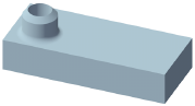
3.Use the Fillet Edge tool to fillet the edge of the solid addition where the round part meets the rectangular shape.
4.Use the Chamfer Edge tool to chamfer the top edge of the round portion.
At this point in the example, the chamfer edge could be edited directly from the Object Info palette. However, to edit an earlier step, you must enter object editing mode to access the object’s nested history.
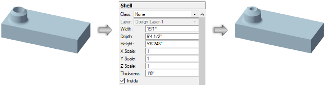
5.To edit the thickness of the shell created in step 2 in this example, do one of the following:
● Select Edit Features from the context menu, highlight a face of the shell, and select Modify Shell from the context menu. Change the shell’s thickness from the Tool bar.
● Select Edit Solid from the context menu two times, so the Object Info palette within object editing mode shows the shell object is to be edited. Change the shell’s Thickness in the Object Info palette.
~~~~~~~~~~~~~~~~~~~~~~~~~