Creating auto hybrid objectsCreating auto hybrid objects
Command |
Workspace: Path |
Create Auto Hybrid |
● Architect: AEC ● Landmark: Landmark > Architectural ● Spotlight: Spotlight > Architectural |
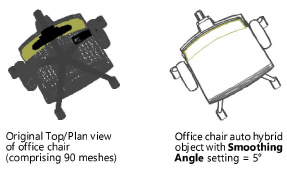
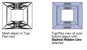
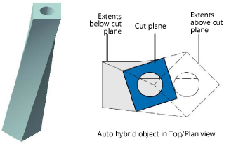
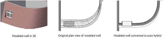
Converting 3D geometry into an auto hybrid object allows the object to appear as desired in 2D plan view, while leaving the 3D appearance unchanged. This is particularly important for Building Information Model (BIM) workflows and for those who model free-form 3D geometry, but need plan drawings as well. The auto hybrid’s settings provide complete control over its 2D display attributes, with separate, classed parameters for the appearance of the cut plane and extents below and above the cut plane.
For an alternative workflow, 2D components can be added to symbols and many plug-in objects, for viewing in hidden line rendered viewports (Concept: 2D components for symbol definitions and plug-in objects). This 2D component functionality is not available for auto hybrid objects. Additionally, section viewports allow you to view extents of 3D objects beyond/below and/or before/above the cut plane (Creating section viewports).
To create an auto hybrid object:
1. Select the 3D geometry to convert to an auto hybrid object.
Valid objects include: extrudes, tapered extrudes, multiple extrudes, extrude along path objects, 3D polygons, sweep objects, meshes, solids, NURBS surfaces, and 3D-only symbols and 3D plug-in objects.
2.If not in Top/Plan view, select View > Standard Views > Top Plan.
The auto hybrid’s 2D appearance settings are only visible in Top/Plan view.
3.With the object selected, select the command.
4.The object is converted into an auto hybrid.
5.To set the location of the cut plane and specify the appearance of the auto hybrid, click 2D Appearance from the Object Info palette.
The 2D Appearance dialog box opens. Click the Cut Plane tab and set the desired parameters.
![]() Click
to show/hide the parameters.
Click
to show/hide the parameters.
6.Click the Below Cut Plane/Above Cut Plane tabs to set the appearance of the auto hybrid below/above the cut plane.
![]() Click
to show/hide the parameters.
Click
to show/hide the parameters.
In the Object Info palette, the Cut Plane Elevation displays the design layer cut plane setting (Vectorworks Architect required) when it is enabled, or allows the cut plane elevation to be set. Select whether to display the 2D only or the 2D and 3D appearance for the auto hybrid object.
~~~~~~~~~~~~~~~~~~~~~~~~~