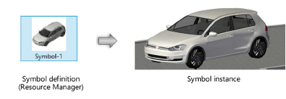
Symbols save objects for reuse. The objects are incorporated into a symbol definition, which is a resource that can be selected from the Resource Manager and Resource Selector. When a symbol definition is placed into the drawing, a symbol instance is created (see Concept: Object instances, definitions, and styles). Vectorworks products provide thousands of symbols as part of the available content. You can also create your own symbols.

A symbol definition can be created from one object or many objects. It may be helpful to review Concept: Objects in the screen plane and in the layer plane.
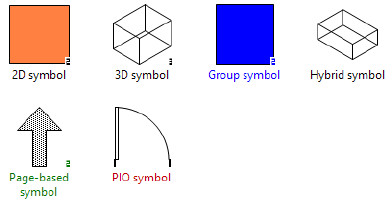
● A 2D symbol definition consists entirely of 2D objects that are created on the screen plane. Examples include text, a rectangle, an arrow, or a bitmap, placed on the screen plane. After placement, the symbol instance exists on any plane (just like any other planar object), and displays in any view.
● A 3D symbol definition consists of 2D and/or 3D objects that are created on a layer plane. Examples include a sphere, an extrude, or a rectangle created on the layer plane. After placement, the symbol instance displays in any view; in Top/Plan view, 3D symbols appear flat.
● A hybrid symbol definition consists of both 2D screen plane and 2D and/or 3D layer plane objects; the placed symbol instance displays the correct component when in Top/Plan and when in a 3D view. For a hybrid symbol instance to display correctly in all views, it must contain at least one screen plane component and a layer plane component. Examples include plug-in objects like a door, wall, or lighting device, or a custom hybrid symbol you have created.
Special symbol definition categories indicate the symbol’s behavior at placement and after placement. These categories are color-coded within the Resource Manager and Resource Selector for identification. The category a symbol definition belongs to depends on the type of objects converted to a symbol definition and the options selected at symbol creation.
● Black: The object parameters from the symbol definition are applied to the instance when it is placed into the drawing; this is the most common type of symbol. The parameters of the symbol instances cannot be modified from the Object Info palette or the Attributes palette. Any changes made to the symbol definition affect all instances of the symbol.
● Red: When placed, this type of symbol definition is converted to a plug-in object. The object parameters from the symbol definition are applied to the instance when it is placed into the drawing, but the parameters of the instance can be modified, with many variations of the same plug-in object in the file. Changes to a red symbol definition affect future instances, but not existing ones.
A red symbol definition can only be created from an existing plug-in object in the drawing. For example, you could insert a plug-in object such as a door, lighting device, or plant (Vectorworks Design Series required), and set its parameters exactly as needed for the project. Save the plug-in object as a symbol definition, and at insertion, the parameters are set as you defined them when the red symbol was created.
● Blue: When placed, this type of symbol definition is converted to a group. Any changes made to the symbol definition later have no effect on existing groups.
If creating a blue symbol definition from geometry or from a plug-in object plus other geometry, keep in mind that the geometry follows the hybrid rules of symbol creation; if the geometry needs to display in all views, it must also be converted to a hybrid symbol first.
● Green: This is a page-based symbol definition that, at insertion, is scaled relative to the page size. Typically these symbols are annotation symbols, such as a North arrow indicator. Any changes made to the symbol definition affect all instances of the symbol.

|
|
Click here for a video tip about this topic (internet access required). |
Symbols provide several advantages.
● Saved properties: Symbol definitions save object properties, such as size, color, and class, within the definition; these properties apply each time the symbol is placed.
● Smaller file sizes: For the most common types of symbol definition, black or green, the definition is stored only once in the drawing file. Placement information (location coordinates, rotation) is all that is required for each symbol instance.
● One-time editing: For the most common types of symbol definition, black or green, changes to the symbol definition automatically update all the instances of the symbol in the drawing.
● Attached database information: The information associated with a symbol instance can be used to generate reports and worksheets. Information attached to a symbol is specific to each instance, allowing each instance to have different record values if needed.
● Ease of import: With the Resource Manager, importing symbol definitions from one file to another is fast and easy, and it includes all the information from the symbol definition.
Plug-in objects are a special type of symbol, created with programming or scripting. They are most similar to red symbols, but they are more powerful; they can be inserted by a tool or with a command, their default parameters can be modified through an associated Settings or Properties dialog box before placement, in addition to the Object Info palette after placement, and, for applicable objects, plug-in object styles can be saved. Plug-in objects are inserted by several tools and commands in the Vectorworks program, such as the Title Block Border tool. In addition, much of the Vectorworks content libraries consist of plug-in objects, which are inserted from the Resource Manager or Resource Selector.
Custom plug-in objects can be created with the Tools > Plug-ins > Plug-in Manager command; see Concept: Scripted plug-ins. In addition, a plug-in object from the drawing can be set up with all the desired parameters, and then it can be saved as a red symbol that becomes a plug-in object upon insertion.
~~~~~~~~~~~~~~~~~~~~~~~~~