 Creating interior elevation viewportsCreating interior elevation viewports
Command |
Path |
Create Interior Elevation Viewport |
View |
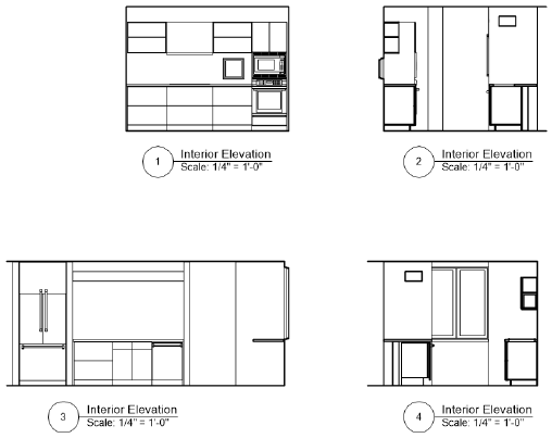
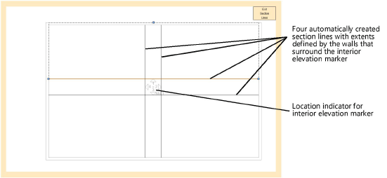
The Create Interior Elevation Viewport command creates as many as four interior elevation viewports of a room or area of a model at the same time. Interior elevation viewports are a kind of vertical section viewport, but rather than creating a cross section of the area, the command creates section lines with extents defined by the walls that surround the interior elevation marker. The drawing’s automatic coordination among the interior elevation marker and the associated viewports is maintained as long as the viewports are kept on the same sheet layer or design layer on which they are originally created.
By default, the vertical extent of the section lines is determined by the bottom of the lowest wall and the top of the highest wall of all layers visible in a sheet layer viewport, or by the height of the active layer for a design layer viewport. By default the horizontal extent is determined by the nearest walls in the XY direction of each section line; if there is no wall in a direction, the extent will be determined by the bounding box of the nearest object. Section lines, which are not visible on the design layer, can be edited after creation by clicking Edit Section Lines from the Object Info palette or by double-clicking the interior elevation marker.
To create interior elevation viewports:
1. Make sure the desired design layer is active (normally, this is the layer which contains the walls), and set the drawing to Top/Plan view.
Once the viewports are created, the interior elevation marker displays on the active design layer. The viewports are connected to this marker for ease of editing and automatic coordination.
2.Select the command.
3.Click once to place the interior elevation marker in the drawing, and click again to set the rotation.
The Create Interior Elevation Viewports dialog box opens to set the viewport properties.
![]() Click
to show/hide the parameters.
Click
to show/hide the parameters.
The interior elevation marker displays on the design layer that was active when you created the viewports. It is updated to reflect which viewports were created, and to display with the selected settings. Associated viewports are placed on the specified sheet layer or design layer. Moving individual viewports to a different layer breaks the association with the interior elevation marker and the other viewports, and the relocated interior elevation viewport is converted to a section viewport.
|
Click here for a video tip about this topic (internet access required). |
