Creating drawing labels
|
Tool |
Tool set |
|
Drawing Label
|
Dims/Notes |

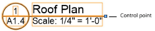
The Drawing Label tool adds descriptive information to a drawing, such as title, scale, and drawing and sheet numbers. Alternatively, when creating a viewport, you can opt to add a drawing label to the viewport annotations.

The alignment modes temporarily override the label’s defined insertion point, for precise placement.
|
Mode |
Description |
|
Align Object Left
|
Insertion point is the left edge of the label’s bounding box |
|
Align Object Center
|
Insertion point is the center of the label’s bounding box |
|
Align Object Right
|
Insertion point is the right edge of the label’s bounding box |
|
Align Object Origin
|
Insertion point is the label’s originally specified insertion point |
|
Style |
Opens the Resource Selector to select a drawing label for placement; double-click a resource to activate it |
|
Preferences
|
Sets the default parameters for the tool |


To add a drawing label:
Click the tool and mode.
Do one of the following:
Click Style on the Tool bar to select a resource from the Resource Selector.
Click Preferences to open the object properties dialog box and specify the tool’s default parameters.
The parameters can be edited later from the Object Info palette.
Click to show/hide the parameters.Click to show/hide the parameters.
|
Parameter |
Description |
|
Style |
Replace the current style with one from the Resource Selector, or use the unstyled option |
|
Hide style parameters |
Hides the parameters that are set by style; these cannot be edited from the properties dialog box or Object Info palette |
|
Scale Factor |
Scales the label larger or smaller by the factor specified |
|
Drawing Title |
Specifies the title text to display in the label. If Use Automatic Drawing Coordination is enabled in the document preferences (Design Suite required), and the label is in a viewport, changes here update the viewport’s drawing title, and vice versa. |
|
Drawing Number |
Identifies this drawing on the current sheet. If the label is in a viewport or sheet layer, the program automatically numbers items and updates this field; this number must be unique on this layer. If the label is on a design layer, enter an identifier manually. |
|
Sheet Number |
Identifies the sheet that contains the drawing. If the label is on a sheet layer, the Sheet Number is displayed by default. If Use Automatic Drawing Coordination is enabled in document preferences (Design Suite required), and the label is on a sheet layer, this field cannot be edited and always contains the Sheet Number. |
|
Note |
Optional text that can be displayed in the label layout |
|
Back Ref. Sheet No. |
Identifies one or more sheets with markers that reference the viewport associated with this drawing label |
|
Scale Display |
Specifies the style of scale information to display on the label: Architectural style (as in 1/4ʺ = 1ʹ- 0ʺ) Engineering style (as in 1:48) Custom uses the Custom Scale text |
|
Label Length Mode |
Controls the length of the drawing label object: Fixed: Length is set to the Printed Length value Auto-Fit: Length is fit to the label’s contents Control Point: Length is set by the control point location
|
Click to place the object, and click again to set the rotation.
Editing drawing labels
Once a label is in the drawing, you can edit it from the Object Info palette. The following additional options are available when editing drawing labels.
|
Option |
Description |
|
Style list options |
Replace: Applies a different style to this object Convert to Unstyled: Allows you to modify the settings and label layout for this object only Edit Style: Allows you to modify the settings and label layout for all objects in the drawing that use the current style See Creating styles for markers and drawing labels for details. |
|
Edit Drawing Label Layout (unstyled labels) |
Opens an editing window to change the geometry and text in the label; see Creating styles for markers and drawing labels |