 Creating styles for markers and drawing labels
The Vectorworks resource libraries provide commonly used marker and drawing label styles. If you need a different style for a specific construction documentation standard, or if you just want a different look, create a custom style. The following types of objects can use styles.
Drawing labels
Reference markers
Section-elevation lines
Interior elevation markers
Detail callouts
Marker and label styles allow you to set fixed values for some of the parameters for all instances that use the style, while maintaining the ability to edit other parameters for each instance of the marker or label. See Concept: Plug-in object styles.
Once a style is created, you can select it from the Resource Selector on the Tool bar (while using a tool to create a marker or label) or while creating a viewport that uses an object of that type.
To create a marker or drawing label style:
Do one of the following:
From the Resource Manager, select an existing resource in the active file to use as a starting point. Right-click on the resource and select Edit from the context menu.
Select an existing marker or label in the drawing to use as a starting point. From the Object Info palette's Style list, select Convert to Unstyled, and then select New Plug-in Style from Unstyled Plug-in. From the Select Folder dialog box, select the destination folder for the style.
The Plug-in Object Style dialog box opens, with the same set of parameters that are used to add an object to the drawing.
Enter a Style Name, and then edit the parameters as desired.
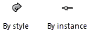
To specify whether each parameter will be set by style or by instance, click Plug-in Style/Instance Settings. On the dialog box that displays, click the By Style column next to a parameter to toggle the setting.
To edit the geometry or text of the object, click Edit Marker Layout, Edit End Marker Layout, or Edit Drawing Label Layout.
In the layout editing window, edit or draw the geometry of the object in page units using any planar graphic tools.
Use the Text tool to add static and/or dynamic text objects to the object. From the Object Info palette, specify the appearance of the text; see Formatting text for more information about the options available.
Static text simply shows the text on each object.
Dynamic text shows information from the drawing (for example, the sheet number) on each object, in place of the text object. To create dynamic text, select the text object and click Use dynamic text from the Object Info palette. Then click the Define Marker Field or Define Drawing Label Field button to open the dialog box and define the field.
Click to show/hide the parameters.Click to show/hide the parameters.
|
Parameter |
Description |
|
Field Label |
Enter the text to display for this field in the layout editing window |
|
Current Field Definition |
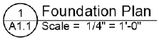
Displays the parameter variables and any text that has been added to the definition. In the label below, the definition for the bottom field looks like this: Scale = #Drawing Label2#.#Scale# where “Scale =” is manually entered text, followed by the Scale variable, which is selected from the Parameter Name list.
|
|
Parameter Name |
Specify a parameter to display on the object for this Field Label. Different options are available for each object type. |
|
Add to Definition |
After you select a parameter, this adds the appropriate variable to the Current Field Definition window |
Use the layout constraints on the Object Info palette to control the positions of the text and 2D objects when the object is rotated, or when the size of the object’s bounding box is different from the defined size.
|
Constraint |
Description |
|
Drawing label |
|
|
Constrain object distance from boundary |
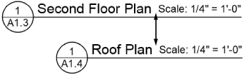
Constrains the distance of the object from the left or right label boundary. Text objects that are horizontally aligned and closely spaced will automatically maintain their defined spacing.
|
|
Fix width |
When deselected, scales the object horizontally to fit the bounding box when necessary; not applicable to text |
|
Reference marker |
|
|
Rotate with marker |
Rotates the object when the marker is rotated |
|
Rotate to arrow angle |
Rotates the object to the marker’s Arrow Angle value |
|
Section-elevation line |
|
|
Rotate with marker |
Rotates the object when the marker is rotated |
|
Flip with section view direction |
Flips the object about the section line when the section view direction is reversed |
|
Keep text display angle |
Maintains the text object angle as defined, even when the marker is rotated |
|
Interior elevation marker |
|
|
Elevation direction graphic/data |
Displays the object and rotates it to each interior elevation view direction |
|
Rotate with marker |
Rotates the object when the marker is rotated |
|
Keep text display angle |
Maintains the text object angle as defined, even when the marker is rotated |
|
Detail callout |
|
|
Rotate with marker |
Rotates the object when the marker is rotated |
|
Keep text display angle |
Maintains the text object angle as defined, even when the marker is rotated |
When you’re done editing the geometry and text fields on the marker, click Exit Marker Layout or Exit Drawing Label Layout and click OK in the Plug-in Object Style dialog box. The new style is added to the Resource Manager for the current file and is now available for use with the appropriate tool.
