 Drawing cable paths
|
Tool |
Tool set |
|
Cable Path
|
Lighting |
Typically, an event space has one area where power and signal cables start for each department. Then, there are one or two fixed paths from this location to the roof, to trusses, to speakers, etc., which break out to the different areas.
The tool creates cable path objects, similar to the Cable Route tool in ConnectCAD, but with additional parameters that are useful for Spotlight and Braceworks users. In Spotlight, the cable path acts as a guide for the physical cables created with the Cable tool. In ConnectCAD, cable paths created by the Cable Route tool act as physical cable routes placed on the model but also as a theoretical route for the circuits defined on the schematic layer.
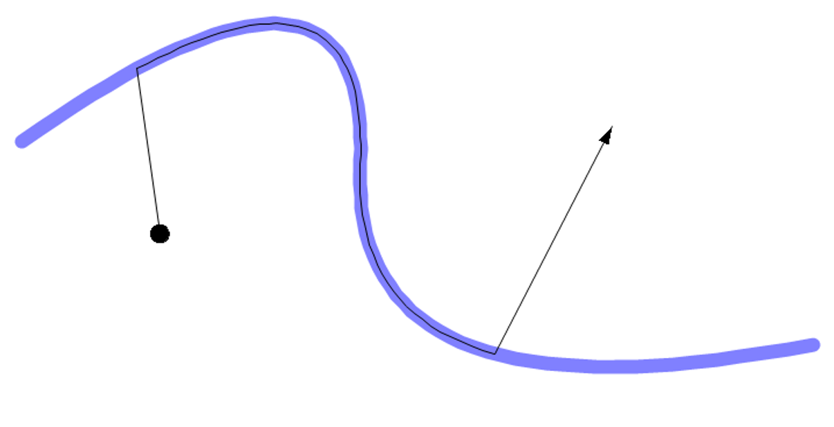
In any view, the Cable Path tool draws a 3D cable path as a template for future cables. By inserting a cable path object, you can avoid redrawing the same path for multiple cable runs. The Cable tool can use all or part of the path. When drawing cables, click on the cable path object at the desired jump-in and jump-out points.
![]()
|
Mode |
Description |
|
Polyline creation options |
Selects the method for drawing the polyline upon which the object is based; see Creating polylines |
|
Fillet Radius
|
For Arc Vertex polyline mode, enter the fillet radius |
|
Automatic Numbering
|
Enables automatic numbering of cable areas as they are placed |
|
Numbering Preferences
|
Set the default parameters for automatic numbering of cable areas |
To draw a cable path:
Click the tool. From the Tool bar, enable Automatic Numbering if desired, and specify the Numbering Preferences. See Automatic numbering preferences.
Select a drawing mode from the Tool bar.
Click to set the cable path’s start point.
Click to set the end of the segment and the beginning of the next. As you place the cable path, compatible objects such as distributors and trusses are highlighted; click to connect (see Concept: Attaching loads to rigging objects). Continue drawing segments in this manner and double-click when the path is complete. Alternatively, convert a custom shape into a generic cable path with the Modify > Create Objects from Shapes command.
When inserting cables with the Cable tool, click on the cable path object to set the cable's entry point. Click again to set the exit point; the cable will exit the path from the point closest to the click point.
The parameters can be edited later from the Object Info palette.
Click to show/hide the parameters.Click to show/hide the parameters.
|
Parameter |
Description |
|
ID |
Provide a unique identifier for labels and paperwork. If blank, a value is automatically assigned when calculations are run (Braceworks required). |
|
Location |
Enter the name of the associated rigging object or other location information for paperwork |
|
Length |
Displays the cable path length |
|
Cable Count |
Displays the number of cables associated with the path |
|
Cable Area (ConnectCAD required) |
Estimates the cross-section area of ConnectCAD circuits; see Creating cable networks |
|
Set 2D Attributes |
Select whether to set the appearance of the cable path by Object (with the Attributes palette) or by Class; if by Class, select the class |
|
2D Attributes Class |
If the attributes of the object are set by Class, select a class from the list of classes present in the drawing, or create a new class |
|
Vertex parameters |
Edits the vertices of the path object that the cable path is based upon; see Editing vertex-based objects |
Reshaping cable paths
Use the Reshape tool to change the route of the cable path; double-click on the cable path to activate the Reshape tool, or right-click on the object and select Edit Path. Any cables that follow the cable path automatically adapt their geometry. When a cable only follows part of the cable path, the cable maintains the same distance from the start and end points of the cable path when it is reshaped.
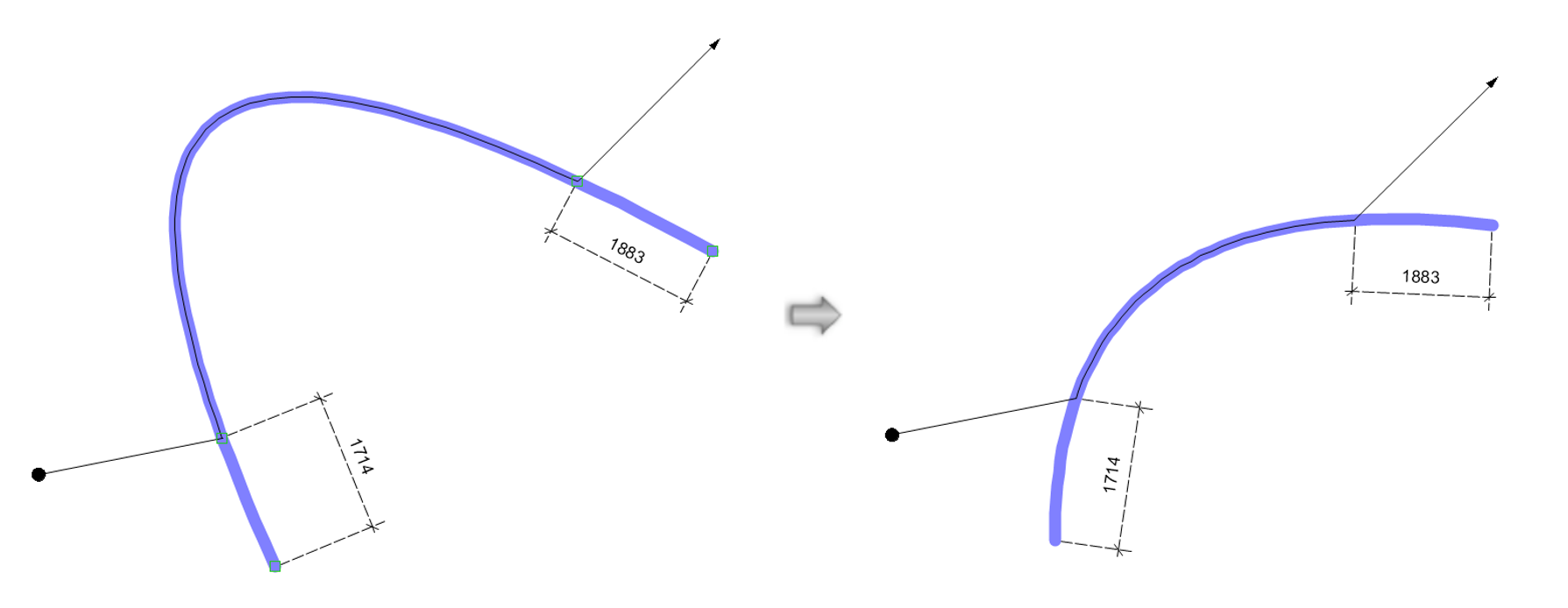
The available Reshape tool modes are identical to those for the NURBS curve (see Reshaping NURBS curves), plus additional sub-modes for the Vertex Move, Add Vertex, and Move Edges Parallel modes. These constraint sub-modes make it easy to reshape the cable path along existing geometry.
![]()
|
Mode |
Description |
|
Unconstrained (Vertex Move and Add Vertex)
|
Allows the vertex to be moved freely in a plane defined by the previous and next points; press the Shift key to snap to the vertical or horizontal plane |
|
Constrain Along Previous Edge (Vertex Move and Add Vertex)
|
Constrains the new or moved vertex along the line defined by the current and previous points |
|
Constrain Along Next Edge (Vertex Move and Add Vertex)
|
Constrains the new or moved vertex along the line defined by the current and next point |
|
Unconstrained (Move Edges Parallel)
|
Allows the edge to be moved freely in a plane defined by the next and previous edge, moving the edge around the selected line; press the Shift key to snap to the vertical or horizontal plane |
|
Constrain in Plane of Previous Edge (Move Edges Parallel)
|
Constrains the edge movement along the direction of the previous edge |
|
Constrain in Plane of Following Edge (Move Edges Parallel)
|
Constrains the edge movement along the direction of the next edge |
|
Auto Heal Paths
|
When reshaping a cable path with Auto Heal Paths toggled on, moving the end of one cable path to the end of another cable path merges the cable paths into a single object. The cable paths will only auto heal when both cable ends are not connected to anything else. When Auto Heal Paths is toggled off, joining the ends of two cable path objects keeps them as separate objects in the cable path network. |
