 Creating cable networks
|
Tool |
Tool set |
|
Cable Route
|
Cable Route |

The Cable Route tool creates networks of cable path objects, laying out the physical location of the cable network and connecting equipment items and drop points. Lay out the planned main cable routes, and then use the same tool to connect drop points and equipment items.
The tool creates cable path objects, similar to the Cable Path tool in Vectorworks Spotlight, but with additional parameters that are useful for ConnectCAD. In Spotlight, the cable path acts as a guide for the physical cables created with the Cable tool. In ConnectCAD, cable paths created by the Cable Route tool act as physical cable routes placed on the model but also as a theoretical route for the circuits defined on the schematic layer.
You can also use the Cable tool from the Cable Route tool set to override the shortest path assigned to a circuit in the cable network. Place a Spotlight cable object and assign it to the circuit in question; the length and routing of the cable object is used instead of the automatically calculated route. Provide a Run ID in the cable's Object Info palette. On the schematic layer, select the circuit to be assigned, and in the circuit's Object Info palette, select the same Cable from the list to assign the cable to the circuit.
![]()
|
Mode |
Description |
|
XY Insertion
|
Draws the cable path constrained to the XY plane (horizontally), at the elevation specified in the Cable Height list |
|
Z Insertion
|
Draws the cable path constrained to the Z axis, which is useful when, for example, you need to follow the slope of a theater seating, or to create detailed vertical shifts around model geometry |
|
Working Plane
|
Draws the cable path along the working plane, such as when drawing cables on a wall. The Set Working Plane tool is available from the Cable Route tool set for convenience. |
|
Join to Existing Routes
|
Toggles between allowing the new cable path to join existing cable paths, which creates a network, or to draw an individual cable path segment that is not connected |
|
Cable Height (XY mode required) |
Specifies the elevation of the cable path when drawing on the XY plane. Select an elevation preset, or open the Edit Cable Route Heights dialog box to specify a custom height. While drawing cable path segments, if a different elevation is specified, a vertical connecting segment is automatically added. Press the mode key (Shift + the mode key to reverse the order) for Cable Height mode (see Modifying special shortcuts) to cycle through the cable path heights while drawing. |
To draw a cable path, optionally connecting it to other cable paths to form a network:
Click the tool and mode. While drawing cable path segments, you will likely need to switch among the modes as you create various segments of the cable path or require varying heights.
In Top/Plan or Top view, use XY Insertion mode and set the elevation of the cable path by selecting a height from Cable Height on the Tool bar. If the height you need is not available, manage the list of available heights by selecting Edit Cable Route Heights from the Cable Heights list. In the Edit Cable Route Heights dialog box, click on a height value to edit it. Click Add to add an additional height, or Delete to remove a selected height entry.
In a 3D view, use Z Insertion mode to draw the cable path at the desired elevations.
If the cable path needs to be constrained to the working plane, use Working Plane mode.
Normally, enable Join to Existing Routes mode to create a network of cable path objects.
Alternatively, convert a custom shape into a generic cable path with the Modify > Create Objects from Shapes command. Customize the cable path later by connecting it to the cable network and adding information in the Object Info palette.
Use the snap loupe to draw cable paths around detailed geometry or to connect to an equipment item's snap point. See Using the snap loupe.
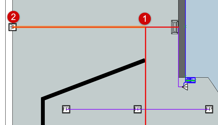
Click to place the start of the cable path, and draw the path polyline, clicking at each vertex. Either click on a connectable object (drop point or other cable path), or double-click to finish drawing the path.
If Join to Existing Routes mode is on, valid cable path objects are highlighted as you draw and can be connected to. When one end of the path is placed on another path, they are connected, and the existing path is split into two.
Editing cable networks
The cable path properties can be edited from the Object Info palette.
Click to show/hide the parameters.Click to show/hide the parameters.
|
Parameter |
Description |
|
ID |
Provide a unique identifier for labels and paperwork |
|
Location |
Enter the name of the building location, associated rigging object or architectural beam, or other location information for paperwork |
|
Length |
Displays the length of the current cable path segment |
|
Cable Count |
Displays the number of cables and circuits associated with the path |
|
Cable Area |
Displays the cross-section area of the cable path (including circuits and cables) |
|
Set 2D Attributes |
Select whether to set the appearance of the cable path by Object (with the Attributes palette) or by Class; if by Class, select the class |
|
2D Attributes Class |
If the attributes of the object are set by Class, select a class from the list of classes present in the drawing, or create a new class |
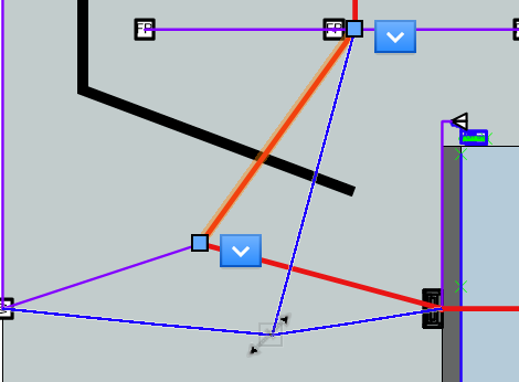
Move the handle on a cable segment to move the entire network of connected cables in the cable path.
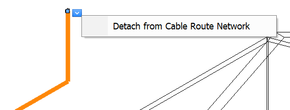
A connected cable path object can be disconnected from the network. Select Detach from Cable Route Network from the drop-down context menu.
Use the Reshape tool to change the route of the cable path; double-click on the cable path to activate the Reshape tool, or right-click on the object and select Edit Path. Connectivity of the cable network is maintained while moving or reshaping cables.
The available Reshape tool modes are identical to those for the NURBS curve (see Reshaping NURBS curves), plus additional sub-modes for the Vertex Move, Add Vertex, and Move Edges Parallel modes. These constraint sub-modes make it easy to reshape the cable path along existing geometry.
![]()
|
Mode |
Description |
|
Unconstrained (Vertex Move and Add Vertex)
|
Allows the vertex to be moved freely in a plane defined by the previous and next points; press the Shift key to snap to the vertical or horizontal plane |
|
Constrain Along Previous Edge (Vertex Move and Add Vertex)
|
Constrains the new or moved vertex along the line defined by the current and previous points |
|
Constrain Along Next Edge (Vertex Move and Add Vertex)
|
Constrains the new or moved vertex along the line defined by the current and next point |
|
Unconstrained (Move Edges Parallel)
|
Allows the edge to be moved freely in a plane defined by the next and previous edge, moving the edge around the selected line; press the Shift key to snap to the vertical or horizontal plane |
|
Constrain in Plane of Previous Edge (Move Edges Parallel)
|
Constrains the edge movement along the direction of the previous edge |
|
Constrain in Plane of Following Edge (Move Edges Parallel)
|
Constrains the edge movement along the direction of the next edge |
|
Auto Heal Paths
|
When reshaping a cable path with Auto Heal Paths toggled on, moving the end of one cable path to the end of another cable path merges the cable paths into a single object. The cable paths will only auto heal when both cable ends are not connected to anything else. When Auto Heal Paths is toggled off, joining the ends of two cable path objects keeps them as separate objects in the cable path network. |
