Bevel gears
|
Mode |
Tool |
Tool set |
|
Modes for The Symbol Insertion tool |
|
Machine Components |

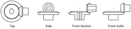
The Bevel Gear tool and Bevel Gear - 3D tool share the same position on the tool set. Click and hold the mouse on the visible tool to open the Pop-out tools list and select the desired tool.
A bevel gear set consists of a gear and pinion.
To insert a bevel gear:
Click the tool and mode.
Click to place the object, and click again to set the rotation. The first time you use the tool in a file, a properties dialog box opens. Set the default parameters. The parameters can be edited later from the Object Info palette.
Click to show/hide the parameters.Click to show/hide the parameters.
|
Parameter |
Description |
|
View (2D only) |
Select the 2D view
|
|
Value to Use |
Select either Diametral Pitch or Module, and then enter the relevant parameter |
|
Diametral Pitch |
Enter the diametral pitch |
|
Module (mm) |
Enter the module |
|
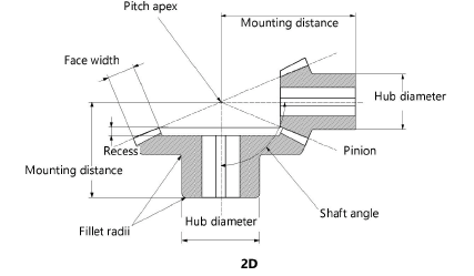
Shaft Angle (deg.) |
Enter the shaft angle in degrees |
|
Face Width |
Enter the face width |
|
Configuration |
Select to use the gear parameter values for only the gear, only the pinion, or for both the gear and the pinion; this can also be used to create miter gears |
|
Gear Properties |
Specify the parameters to draw the gear |
|
No. of Teeth |
Enter the number of teeth |
|
Pitch Dia. (Ref.) |
Displays the pitch diameter based on the diametral pitch and number of teeth |
|
Mounting Distance |
Enter the distance from the back of the gear to the pitch apex |
|
Hub Diameter |
Enter the hub diameter |
|
Hub Projection |
Enter the hub projection, for styles with a projected hub |
|
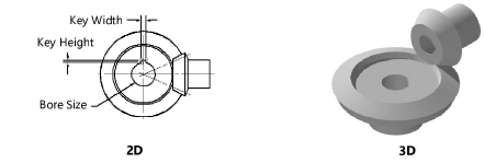
Bore Diameter |
Enter the bore diameter |
|
Key Type |
If the gear includes a keyway, select keyway shape (with ASME-recommended sizes), or select Custom size |
|
Kwy Width/Height |
For custom keyway sizes, enter the keyway width and height |
|
Recess |
If the gear has a recess, enter the recess value |
|
Fillet Radius |
Enter the fillet radius of the hub |
|
Pinion Properties |
For pinion only or gear and pinion configurations, specify the pinion parameters |
|
No. of Teeth |
Enter the number of teeth |
|
Pitch Dia. (Ref.) |
Displays the pitch diameter based on the diametral pitch and number of teeth |
|
Mounting Distance |
Enter the distance from the back of the pinion to the pitch apex |
|
Hub Diameter |
Enter the hub diameter |
|
Hub Projection |
Enter the hub projection, for styles with a projected hub |
|
Bore Diameter |
Enter the bore diameter |
|
Key Type |
If the pinion includes a keyway, select keyway shape (with ASME-recommended sizes), or select Custom size |
|
Kwy Width/Height |
For custom keyway sizes, enter the keyway width and height |
|
Recess |
If the pinion has a recess, enter the recess value |
|
Fillet Radius |
Enter the fillet radius of the hub |
|
Show Pinion at Left (2D only) |
Displays the pinion on the left side of the bevel gear |
|
Draw Center Lines (2D only) |
Draws the bevel gear with center lines |
|
Show Teeth (3D only) |
Draws the bevel gear with teeth
|
|
Spiral Angle (Deg.) (3D only) |
Draws a 3D spiral bevel gear; specify the spiral angle degrees for the teeth |