Gears
Gears
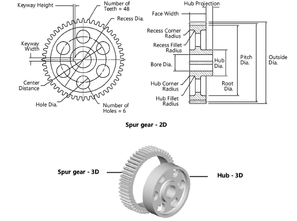
Spur gears
|
Mode |
Tool |
Tool set |
|
Modes for The Symbol Insertion tool |
Spur Gear
|
Machine Components |


Multiple spur gear, spur gear rack, and hub tools share the same position on the tool set. Click and hold the mouse on the visible tool to open the Pop-out tools list and select the desired tool.
To insert a spur gear:
Click the tool and mode.
Click to place the object, and click again to set the rotation. The first time you use the tool in a file, a properties dialog box opens. Set the default parameters. The parameters can be edited later from the Object Info palette.
If you inserted a 3D spur gear, click the Hub - 3D tool from the Machine Components tool set to insert a 3D hub. Place the hub in the drawing and set the default properties, if prompted.
Click to show/hide the parameters.Click to show/hide the parameters.
|
Parameter |
Description |
|
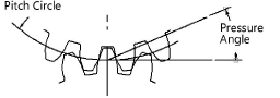
Pitch Diameter |
Specify the pitch diameter |
|
Number of Teeth |
Enter the number of teeth |
|
Pressure Angle |
Enter the pressure angle
|
|
Diametrical Pitch (Ref.) |
Displays the diametrical pitch (for reference only) |
|
Module (mm) (Ref.) |
Displays the module (for reference only) |
|
Outside Dia. (Ref.) |
Displays the outside diameter (for reference only) |
|
Root Dia. (Ref.) |
Displays the root diameter (for reference only) |
|
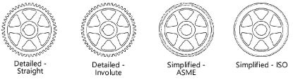
Tooth Profile |
Select the type of tooth profile
|
|
Face Width |
Enter the width of the gear face |
|
Helix Angle (3D only) |
Indicate the 3D spur gear helix angle |
|
Hole Diameter (3D only) |
Indicate the hole diameter for the 3D spur gear; when including a hub 3D object in the drawing, adjust the spur gear hole diameter and hub outside diameter to fit together |
|
Draw Recess (2D only) |
To draw a recessed web, select Draw Recess and specify the 2D parameters |
|
Web Thickness |
Enter the web thickness |
|
Recess Diameter |
Enter the recess diameter |
|
Recess Corner Radius |
Enter the recess corner radius |
|
Recess Fillet Radius |
Enter the recess fillet radius |
|
Draw Hub (2D only) |
Draws a hub |
|
Hub Diameter |
Enter the hub diameter |
|
Hub Projection (Left/Right) |
Specify the amount of projection for the hub on both the left and the right; a negative value indicates that the hub face is recessed |
|
Hub Corner Radius |
Enter the hub corner radius |
|
Hub Fillet Radius |
Enter the hub fillet radius |
|
Draw Bore (2D only) |
Draws a bore |
|
Bore Diameter |
Enter the bore diameter |
|
Keyway |
If a keyway is present, select the square, rectangular, or custom size; the square and rectangular selections apply the ASME-recommended size based on the bore diameter |
|
Width/Height |
For custom keyway sizes, enter the width and height values of the keyway |
|
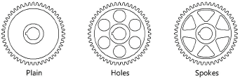
Web Configuration (2D only) |
Select the web configuration and then specify the 2D parameters, if any. When Holes is selected, hole size can be specified as a percentage or diameter value.
|
|
Number |
Indicate the number of holes or spokes for the gear (does not apply to Plain web configurations) |
|
Size (10–100%) |
For Holes (Percent) and Spokes web configurations, enter the percentage of the recess opening occupied by the holes or spokes |
|
Center Distance |
When Holes is selected for the web configuration, specify the distance between the hole centers |
|
Hole Diameter |
When Holes is selected for the web configuration, indicate the size of the holes |
|
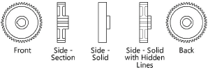
View (2D only) |
Select the 2D view
|
|
Show Center Lines (2D only) |
Draws the 2D gear with center lines |