 Workflow: Creating lighting device symbol definitions
If you are an advanced user, and the lighting device symbol you need is not available, use this workflow to create a custom symbol definition. If you want to create a multi-cell lighting device symbol, see Workflow: Creating multi-cell symbol definitions.
The following workflow applies to single-cell lighting devices. It describes how to create and align the device's 2D and 3D geometry, combine the 2D and 3D versions into a hybrid symbol, and attach the record data needed for lighting functionality.
The numbered steps must be followed in sequence, but the order of the bulleted steps is more flexible. As noted below, some bulleted steps may not apply to your device.
Once the lighting device symbol definition is created, use the Lighting Device tool to place a lighting device symbol instance on the light plot.
Creating the 3D geometry
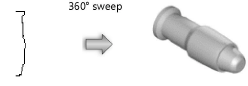
Draw the lighting device’s 3D geometry.
Alternatively, you can create the 2D symbol geometry first; see Creating the 2D geometry. This is helpful if you want to sweep the 2D geometry to create the 3D geometry.
The geometry should be simple and accurately sized. Do not include details like handles, cords, and knobs. These items are not necessary, and they can take a long time to render.
The 3D symbol should consist of five main components. Some additional components are optional. The component specifications are described here:
To reduce file size, the 3D components should consist of 3D solids. Avoid using meshes or NURBS objects. Instead, use extrudes, sweeps, additions, subtractions, and so on. If you perform multiple operations to shape a component, convert it to a generic solid when completed. See 3D modeling for more information about 3D modeling tools and commands.
Set the fill color to Cool Gray 90% for all components (this color is available from the Standard Vectorworks Colors palette).
Apply the default texture to all components. From the Resource Manager, search for “Default Instrument Texture” to locate the black, white, and silver options.
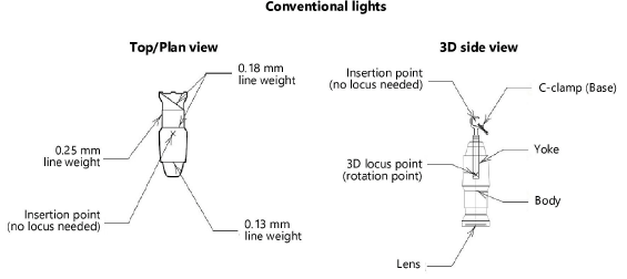
Required 3D components
The 3D geometry should consist of five main parts: body, lens, 3D locus for rotation, yoke, and base. A single part may contain multiple sub-parts; see Attaching the Parts record to the lighting device for details.
The body is the part of the lighting device where light is emitted.
If you have already created the 2D geometry, you can generate a reasonable 3D device body by sweeping the 2D geometry. The segment angle of the sweep should be between 20° and 40°; see Sweeping objects.
Add a lens to the body. This can be a simple extruded circle of 1 mm protruding from the body. The fill color should be RGB (204, 254, 255).
Place a 3D locus within the body at the rotation point for the yoke. (This point also defines where the light is emitted, unless additional 3D loci are used for emitters; see Optional 3D components.) The X,Y coordinates must be 0,0 exactly, or unexpected behavior can result.
The yoke connects the body to the base.
The base consists of either a base motor unit for moving lights or a clamp or other hanging device for conventional lights.
Optional 3D components
Some additional 3D components are optional: multiple light emitters, an input tail for export to the Vision program, and a separate accessory symbol.
Create multiple light emitters by placing a 3D locus for each emitter within the body, at the point of light emission.
Adding multiple emitters can significantly slow the rendering.
One or more accessories can be added directly to the 3D geometry, so the lighting device is always inserted with the accessories attached. For example, use the Symbol Insertion tool to add a clamp symbol to the base. See Concept: Lighting accessories for more information about accessories.
If exporting to Vision, add a 3D input tail for the power connection. This should be an extruded rectangle 100 mm long, 50 mm wide, and 50 mm high.
Orienting the 3D components
Draw the lighting device as if were hanging straight down. The end of the device that emits light should point down along the Z axis. The yoke should be oriented along the Y axis. The top of the lighting device should point to the top of the drawing.
Creating the 3D symbol definition
Create a symbol definition from the 3D geometry and position it for correct insertion.
To create the 3D symbol:
Select all 3D components and select Modify > Create Symbol.
The Create Symbol dialog box opens; see Creating symbol definitions for an explanation of the parameters.
Select Next Mouse Click for the Insertion Point.
After closing the dialog box, click on the 3D symbol at the desired insertion point. This will be the device’s hanging point.
In the drawing, position the 3D symbol at the center of the coordinate system so the insertion point aligns with the 0,0,0 point. You may need to adjust the view to position the device correctly in 3D.
The following are standard insertion points:
Yoked devices: Top center of the yoke or bottom center of the pipe attachment point
Moving devices: Bottom center of the base
Because the symbol’s X,Y rotation point must be 0,0, the insertion point may not be the exact center of the hanging device or base.
Attaching the Parts record to the lighting device
The Parts record is required for proper 3D rotation of the lighting device. Attach the Parts record to each of the five main component parts: base, yoke, body, lens, and 3D locus (rotation point). If adding accessories such as clamps or adding 3D loci for emitters, attach the Parts record to these parts too. See Attaching record formats to symbols, objects, and materials for more information.
Some parts can be made from a group of objects. Each object within the group will use the Parts record that was attached to it individually. If none is attached individually, that object will use the Parts record attached to the group.
Grouping is not necessary for Parts record attachment. Do not group an accessory with any other part.
To attach the Parts record:
From the Resource Manager, locate a Parts record from one of the lighting device library files included with Spotlight, and drag it to the active file. Alternatively, right-click on the record, and select Import from the context menu.
Select the 3D symbol, and select Modify > Edit Symbol.
In the Edit Symbol window, select the base, yoke, 3D locus (rotation point), or accessory.
For each of these components individually, do the following:
Click the Data tab on the Object Info palette. Click Attach Record to open the Resource Selector, and double-click the Parts record to attach it.
Select the appropriate part from the record fields (Base, Yoke, or Point).
Clamps should be defined as Base parts.
In the Edit Symbol window, select the lens.
Repeat step 4 for the lens (select Lens from the record fields).
In the Edit Symbol window, select the body.
The body part can be a group. For example, group the lens and body geometry to form the body, and select this grouped body part.
Repeat step 4 for the body (select Body from the record fields).
For symbols that contain 3D loci for light emitters, select each locus point individually and do the following:
Click the Data tab on the Object Info palette. Click Attach Record to open the Resource Selector, and double-click the Parts record to attach it.
Assign a Light Emitter value of 1 to each 3D locus (emitter).
If the Light Emitter value is not 1, the emitter is not created.
Click Exit Symbol at the upper right corner of the window to return to the drawing.
The bounds of the lighting device symbol are calculated in the device’s home position, with no rotation, and include any added accessories.
Creating the 2D geometry
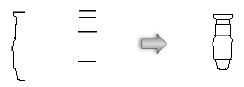
Draw the lighting device’s 2D geometry.
Create a simple line drawing with as few lines and polygons as possible. Try using a single polyline instead of individual line segments. The symbol below was created from these few constituent parts:
Optionally, use the Convert Copy to Lines command to convert the 3D symbol geometry into a simple 2D representation. Delete any extraneous lines. If the lighting device is yoked, remove the yoke geometry.
The size of the lighting device should be accurate based on the real device it represents. Keep the level of detail as minimal as possible. The goal is to distinguish one lighting device from another, not to create a detailed plan view of each device.
For lighting devices with multiple configurations, it is acceptable to use simple graphical differences to distinguish among the models. For example, use the following variations for the different versions of a symbol:
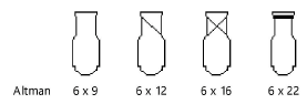
Normally, do not include text labels with the lighting device; these are handled by the object’s label legend; see Setting up label legends. An exception can be made to distinguish different models or lamps of a lighting device. For example, create three versions of a single PAR64 symbol by adding MFL, WFL, and NSP text blocks.
Due to font and scaling issues, the graphical representation described by USITT typically works better than text.
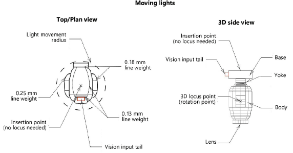
For moving lights, draw a circle around the lighting device to denote the light movement radius. Use a dashed line type. Place the circle’s center point at the device insertion point, and draw the radius to the correct length for the light to sweep.
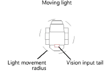
If exporting to Vision, add an input tail where the lighting device will receive power. Draw a rectangle 100 mm long and 50 mm wide to represent the Vision input tail. This connection point can help you orient the symbol correctly in Vision.
Specify the line weights so the device stands out when printed. The outer perimeter of the symbol should have a line weight of at least 0.25 mm. Interior details should use a lighter line weight, such as 0.13 mm or 0.18 mm.
Use a solid fill for all 2D components.
The end of the device that emits light should point to the top of the drawing in Top/Plan view.
Aligning the components
All the parts should be aligned as shown; the yoke rotates about the Z axis, and the body rotates at the height of the 3D locus point.
Creating the hybrid symbol definition
Combine the 2D and 3D geometry to create the hybrid lighting device symbol.
To create the hybrid symbol definition:
Align the 2D and 3D versions of the symbol so the insertion points line up.
The 2D insertion point is also the hanging point.
Select all 2D and 3D components, and select Modify > Create Symbol.
The Create Symbol dialog box opens; see Creating symbol definitions for an explanation of the parameters. Symbols should be named with the model name of the lighting device.
Attaching the Light Info Record
Attach the Light Info Record to the lighting device symbol. This record format is required, but you don't need to fill in every field. Enter the desired default values for the lighting device object, including as much manufacturer data as possible.
If the device will be used in imperial drawings, enter the frame size in Frame Size Imp and type lb after the value in the Weight field.
If the device will be used in metric drawings, enter the frame size in Frame Size Metric and type kg after the value in the Weight field.
To attach the Light Info Record:
From the Resource Manager, locate the Light Info Record from one of the lighting device library files included with the Spotlight program, and drag them to the active file. Alternatively, right-click on the records, and select Import from the context menu.
Select the new symbol, and select Modify > Edit Symbol.
In the Edit Symbol window, click an empty location so that nothing is selected.
Click the Data tab on the Object Info palette. Click Attach Record to open the Resource Selector, and double-click the Light Info Record to attach it. Enter its record information.
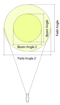
The Candlepower, Beam Angle, and Field Angle parameters affect the photometric grid and photometer object calculations. The Beam Angle and Field Angle parameters affect the Draw Beam feature.
Click Exit Symbol at the upper right corner of the window to return to the drawing.
As an alternative to the process of manually editing the symbol definition to attach the Light Info Record, use the Lighting Symbol Maintenance command as described in Lighting symbol maintenance. Add the symbol by clicking New, and the Light Info Record is automatically attached to it. Once in the maintenance list, the record data can be easily edited for the associated symbol definition.M
