Workflow: Creating multi-cell symbol definitions
If you are an advanced user, and the multi-cell lighting device symbol you need is not available, use this workflow to create a custom symbol definition.
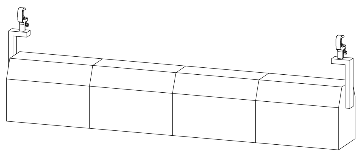
A multi-cell symbol definition combines individual cell symbols to form a container symbol. For example, this four-cell strip light consists of four nested cell symbols: one left, two center, and one right. Depending on the device, some cell symbols can be duplicates. In this strip light, the two center cell symbols are identical.
The following workflow describes how to create the nested cell symbol definitions and combine them to form the multi-cell container symbol definition. The process of creating each cell symbol is similar to creating an individual lighting device symbol (see Workflow: Creating lighting device symbol definitions), but there are important distinctions.
The numbered steps must be followed in sequence, but the order of the bulleted steps is more flexible. As noted below, some bulleted steps may not apply to your device.
Creating the cell symbol definitions
Create a cell symbol definition for each cell in the device. Creating a symbol for each cell allows you to control each circuit independently. This means that a three-circuit device will have three cells, each with independent color control. Check the device's cut sheet to see how many cells (or circuits) and lamps are needed.
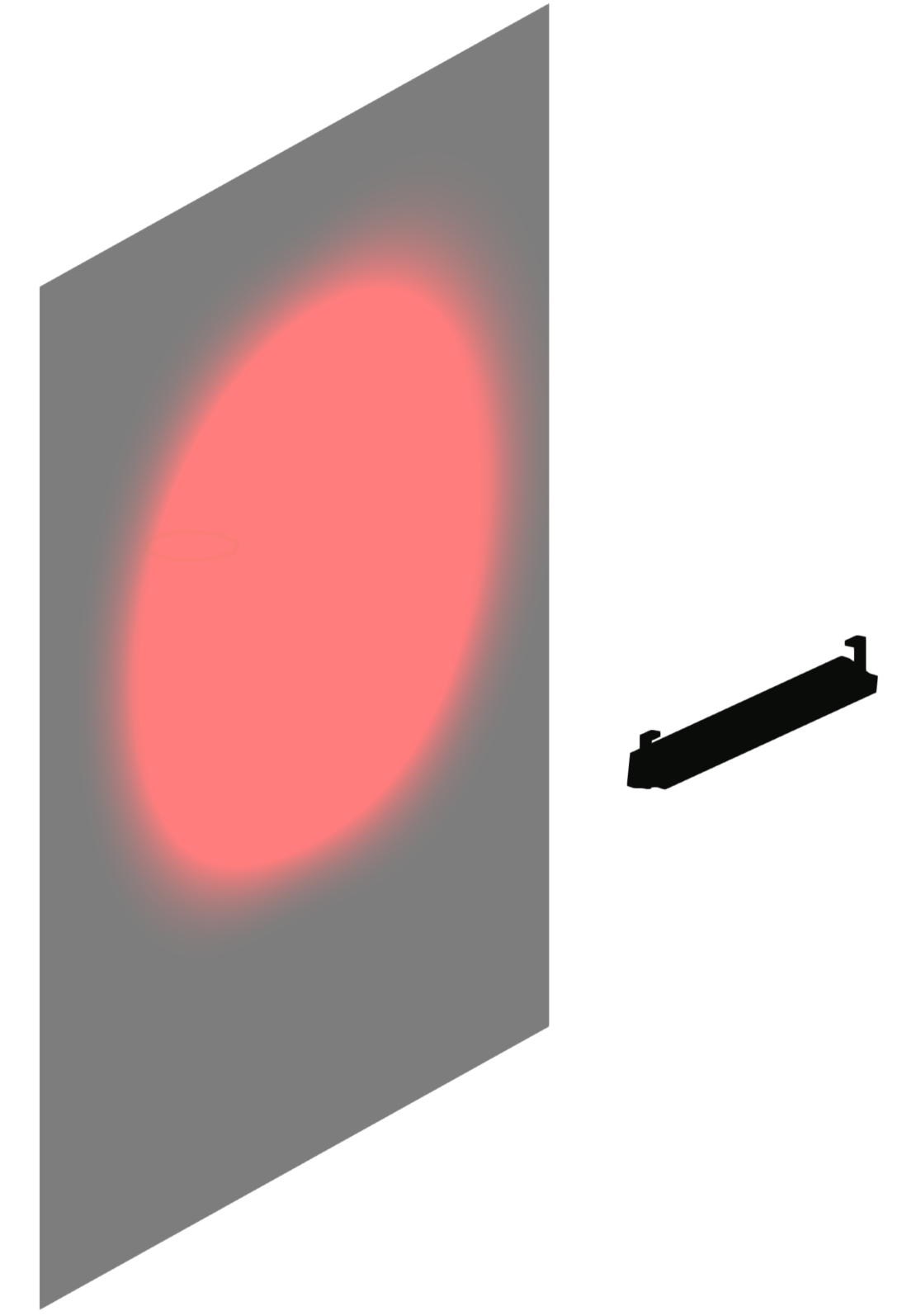
As you create each cell symbol, keep in mind where it fits within the complete multi-cell device. For example, a cell may contain part of the yoke even if the yoke hardware is not directly attached to the cell's housing.
Each cell in the cyc light contains its portion of the yoke
As an alternative to creating each cell symbol from scratch, use the cell symbols in the Vectorworks libraries. Check the available content to see if it meets your needs. Navigate to Libraries\Objects - Ent Lighting Instruments to find the content for a specific multi-cell lighting manufacturer. Open the corresponding .vwx file. If cell symbols are available, they are listed as "zNested Parts." If you decide to use the zNested symbols instead of creating your own cell symbols, you can skip the steps in Creating the cell symbol definitions and proceed to Creating the multi-cell container symbol definition.
Creating the 3D cell geometry
Each cell has a few required parts. A cell may have additional parts, depending on the multi-cell device and the cell's position in it. The parts must be drawn in a certain way and in a suggested order, as described below.
Drawing requirements
To reduce file size, the 3D components should be made of 3D solids. Avoid using meshes or NURBS objects. Instead, use extrudes, sweeps, additions, subtractions, and so on. If you perform multiple operations to shape a component, convert it to a generic solid when completed. See 3D modeling for more information about 3D modeling tools and commands.
The geometry should be simple with accurate dimensions. Do not include details like handles, cords, and knobs. These items are not necessary, and they can take a long time to render.
Draw the cell as if the multi-cell device were hanging straight down. The end of the cell that emits light should point down along the Z axis. The yoke should be oriented along the Y axis.
Set the fill color to Cool Gray 90% for all components (this color is available from the Standard Vectorworks Colors palette).
Apply the default texture to all components. From the Resource Manager, search for "Default Instrument Texture" to locate the black, white, and silver options.
3D cell components
Each cell must include a body, lens, and a 3D locus point for rotation.
At least one cell in the device must have a yoke. If the yoke spans several cells, you can include the entire yoke in a single cell symbol, or include only a portion of the yoke in each cell symbol. It's recommended that you create the yoked cell symbols before creating the unyoked cell symbols.
Depending on the type of device, one or more cells may have a base part. Predefined accessory symbols, such as clamps, can be added directly to the cell geometry.
Light emitters will be added in a later step.
To create the 3D cell geometry:
Draw a body as the main housing of the light.
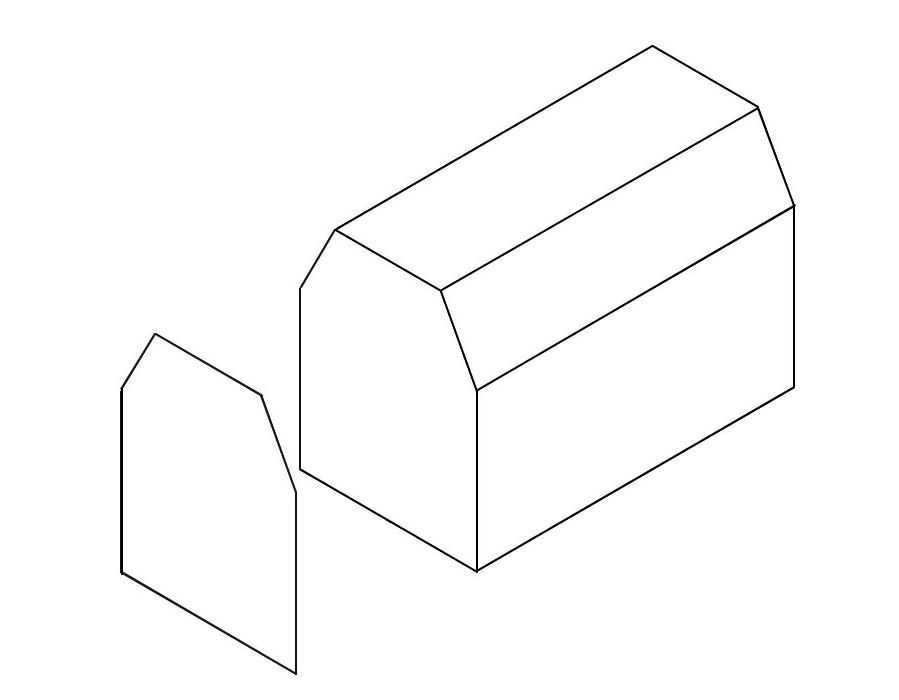
2D polygon extruded to create the body
Add a lens to the body. This can be a simple extruded circle of 1 mm at the front of the body. The fill color should be RGB (204, 254, 255).
A cell may have multiple lenses. Use the Align and Distribute tool to duplicate and distribute the lenses within the cell.
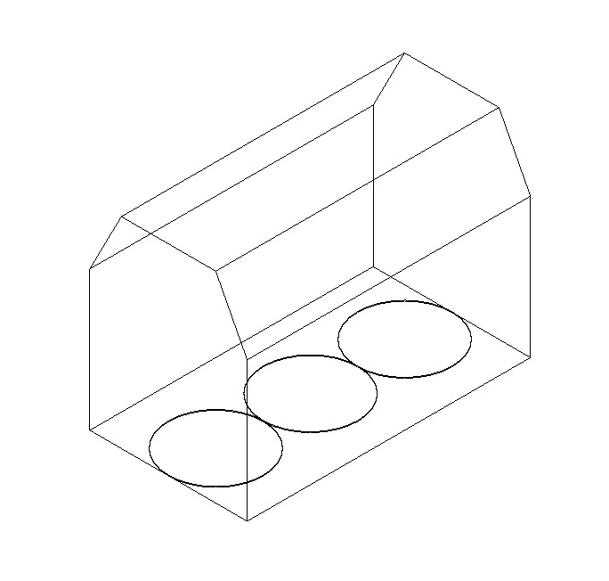
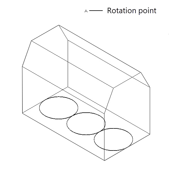
Three extruded circles serve as lenses; the cell is pointing downward on the Z axis
If needed, add a yoke to the body, to connect the body to the base.
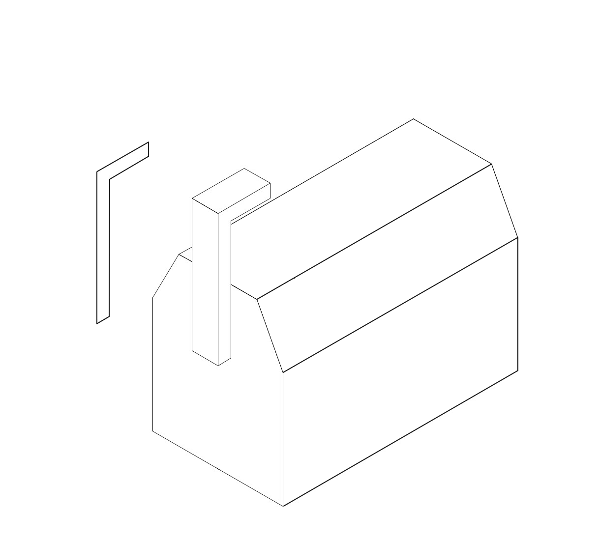
2D polygon extruded to create a hanging yoke
If needed, add a clamp or other mounting hardware as the base.
You can draw the hardware, or use the Symbol Insertion tool to insert a clamp accessory symbol. See step 6 for more information about using accessory symbols.
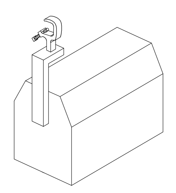
Clamp added to the yoke
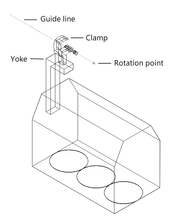
Place a 3D locus within the body at the rotation point for the cell.
The cell rotates about the yoke. If the cell you're creating is not yoked, use a guide line to identify where the rotation point is located on a yoked cell; note the height of this point within the cell. Then, in the unyoked cell, place the 3D locus at the same height and center it between the left and right sides of the cell.
In a yoked cell, locate the rotation point for the yoke
In the unyoked cell, place a 3D locus at this rotation point, centered between the ends of the cell
If desired, add one or more accessory symbols to the cell's 3D geometry. The accessory symbols must have the Parts record and Light Info record attached for proper functionality; see Workflow: Creating accessory symbol definitions for details.
Creating the 3D cell symbol
Create a symbol from the 3D geometry and position it for correct insertion.
To create the 3D symbol:
Select all 3D components and select Modify > Create Symbol.
The Create Symbol dialog box opens; see Creating symbol definitions for an explanation of the parameters.
Select Next Mouse Click for the Insertion Point.
After closing the dialog box, click on the 3D symbol at the desired insertion point. All of the cell symbols should have the same relative insertion point, so they line up in the container symbol.
In the drawing, position the 3D symbol at the center of the coordinate system so the insertion point aligns with the 0,0,0 point. You may need to adjust the view to position the device correctly in 3D.
Attaching the Parts record to the cell symbol
The Parts record is required for proper rotation of each cell symbol. Complete the following steps to attach the Parts record to the cell’s lens, body, and 3D locus point—and to the base, yoke, and accessories if they are present in the cell. (Later in the workflow, you will attach the Parts record to the multi-cell container symbol to define the device rotation point and specify which cell controls each light emitter.)
Some geometry must be grouped together, with a record applied to the group.
Do not group an accessory with any other geometry.
To attach the Parts record:
From the Resource Manager, locate a Parts record from one of the lighting device library files included with Spotlight, and drag it to the active file. Alternatively, right-click on the record, and select Import from the context menu.
Select the 3D symbol, and select Modify > Edit Symbol.
If the cell contains a yoke, base, or accessory, do the following for each of these parts individually. Otherwise, proceed to step 4.
In the Edit Symbol window, select the part.
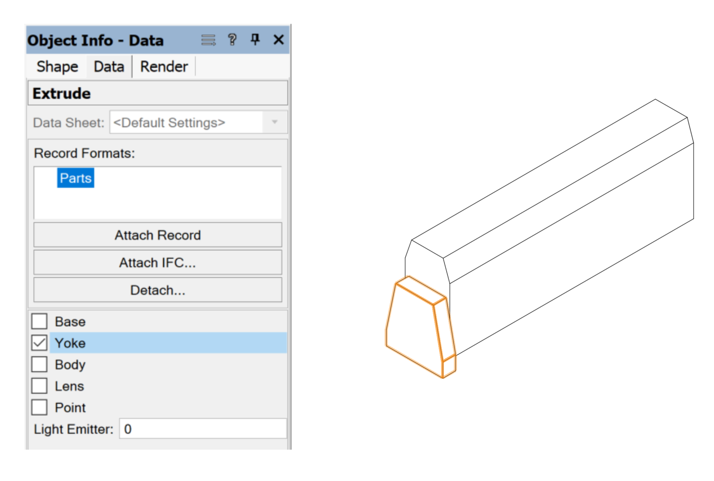
Click the Data tab on the Object Info palette. Click Attach Record to open the Resource Selector, and double-click the Parts record to attach it.
Select the appropriate part from the record fields: Yoke or Base.
If a part is used for tilting the multi-cell device (moving it along the X axis), that part must be defined as a Yoke. This includes the typical yoke hardware for hanging devices, but also the feet on floor-mounted devices. While the feet provide a base for the device, they must be defined as Yoke parts because the device uses them to tilt.
The foot on a floor-mounted cell symbol is defined as a Yoke part
Clamp accessories are considered Base parts.
Repeat step 3 for the 3D locus. Select Point from the record fields.
Repeat step 3 for the lens. Select Lens from the record fields.
If the cell has more than one lens, you can group the lenses and attach the record to the group.
In the Edit Symbol window, group the lens (or the lens group) with the body geometry to form the body part.
With the grouped body part selected, repeat step 3 for the body. Select Body from the record fields.
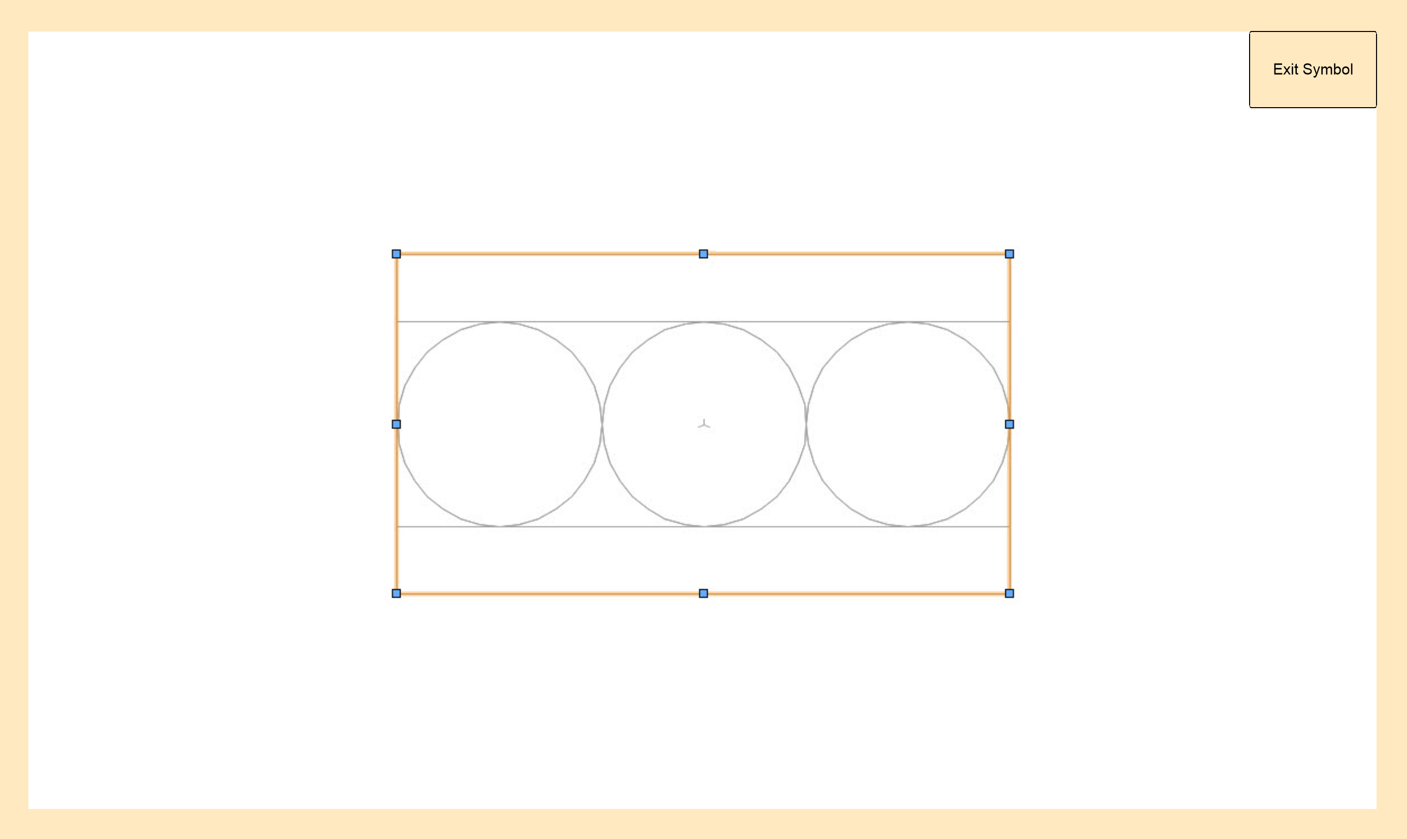
Click Exit Symbol at the upper right corner of the window to return to the drawing.
Creating the hybrid cell symbol
Draw the cell's 2D geometry. The cell symbols will need to align in the multi-cell container symbol, so it's important to make the 2D geometry consistent for all cells.
If one cell hangs under another cell that blocks it in 2D views, the under-hung cell symbol does not need a 2D representation.
Automatically generate a simple line drawing that outlines the 3D components:
Select the 3D cell symbol, and select Edit 2D Components from the context menu.
The Object editing mode opens. In the Component Edit palette, set the Edit component to Top and set the Show Other view to 3D.
Select Generate 2D from 3D Component from the context menu, and select the line rendering style for the 2D component.
The 2D geometry is created on top of the 3D geometry, so the two versions are automatically aligned
If needed, edit the 2D components as described in Creating 2D components for symbol definitions and plug-in objects. Set the line weights so the cell stands out when printed. The perimeter of the symbol should have a line weight of at least 0.25 mm. Interior details should use a lighter line weight, such as 0.13 mm or 0.18 mm.
Click Exit Symbol to close the editing window. An alert opens; click Yes to confirm that you want to create a hybrid symbol.
In the drawing, position the hybrid symbol at the center of the coordinate system so the insertion point aligns with the 0,0,0 point. You may need to adjust the view to position the device correctly in 3D.
Attaching the Light Info Record to the cell symbol
The Light Info Record is required for each cell symbol. Attach the Light Info Record, as described in Attaching the Light Info Record, but only fill in the data specific to the cell: 3D Symbol Name, Wattage, Lamp, Device Type, Beam/Field Angle, Candlepower, and Num Channels. For now, ignore any fields that apply to the whole multi-cell lighting device, such as Position and Weight. You will specify these global device data in the Light Info Record and additional records when creating the multi-cell container symbol definition.
Creating the multi-cell container symbol definition
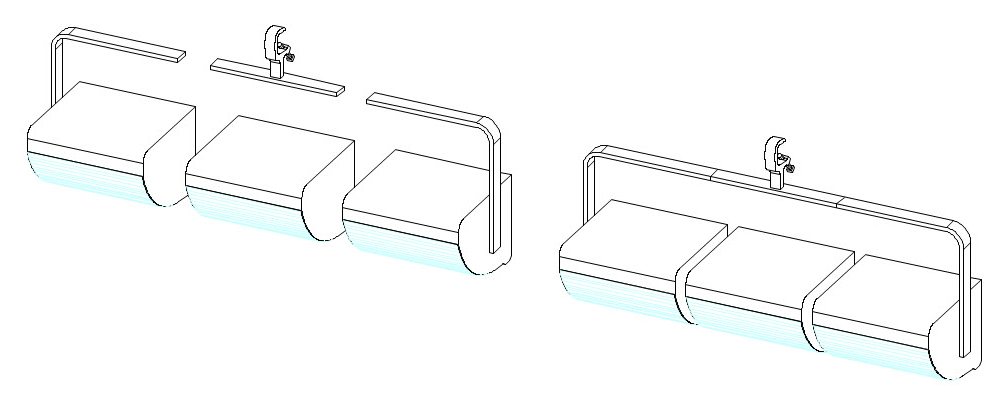
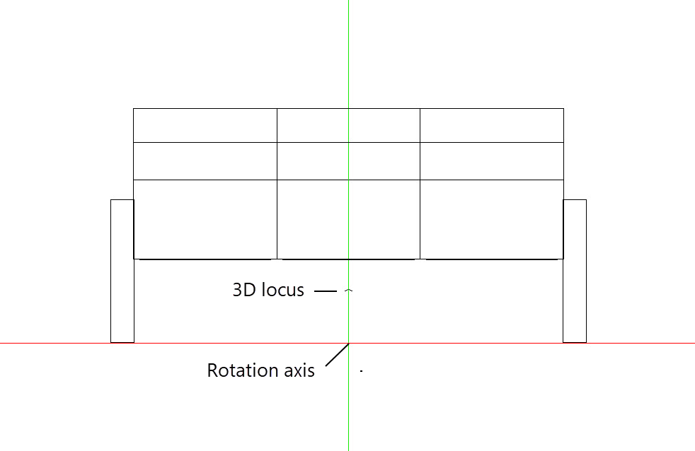
The container symbol is created by aligning the individual cell symbols to form the multi-cell device. Once the cells are correctly aligned, 3D loci are added to define the light emitters and the rotation axis of the device, and the necessary record data is attached.
Multi-cell lighting devices rotate in 3D just like individual lighting devices. The yoke (made from portions of the nested cell symbols) is the means of rotation. A 3D locus point placed in the container symbol defines the axis of rotation.
Floor-mounted multi-cell symbol
To create the container symbol:
Use the Symbol Insertion tool to place the individual cell symbols on the design layer, aligned as needed for the multi-cell device.
Alternatively, locate the cell symbols in the Resource Manager and drag them to the drawing. Do not double-click the cell symbols in the Resource Manager or use the Lighting Device tool to insert them.
The order in which you place the cell symbols determines their index numbers. This is important for selecting and editing the cells in the drawing. The first symbol placed is cell #1, the second is cell #2, and so on. See Concept: Multi-cell lighting devices for more information about index numbers.
Place a 3D locus point in the multi-cell device at the rotation point for the yoke.
Select all the cell symbols and select Modify > Create Symbol to create the container symbol.
The Create Symbol dialog box opens; see Creating symbol definitions for an explanation of the parameters.
Select Next Mouse Click for the Insertion Point.
After closing the dialog box, click on the 3D symbol at the desired insertion point.
In the drawing, position the 3D symbol at the center of the coordinate system so the insertion point aligns with the 0,0,0 point. You may need to adjust the view to position the device correctly in 3D.
Attaching the Parts record to the container symbol
The Parts record defines the rotation point for the multi-cell device and also defines the controller cell for each light emitter.
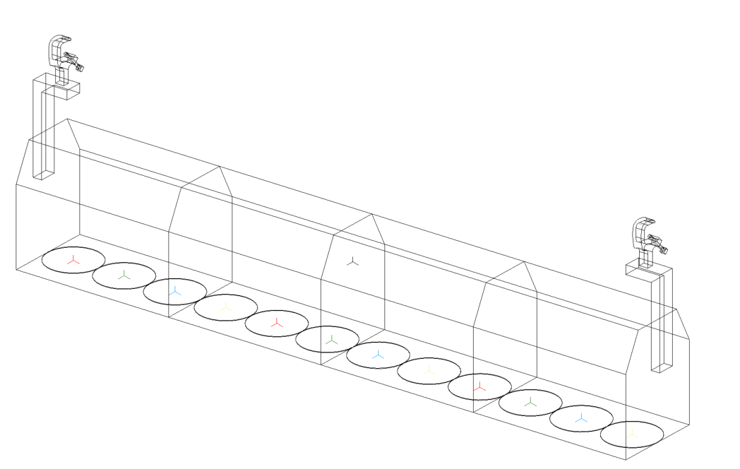
Multi-cell symbols can support multiple light emitters when rendering. Each emitter is associated with a 3D locus point. The 3D locus sets the precise location of the light source. When the Parts record is attached to the 3D locus (light emitter), the record's Light Emitter value determines which cell controls the emitter. All 3D loci with the same Light Emitter value will have the same light properties, as set by the controller cell. This is true even if the emitters are in different cells.
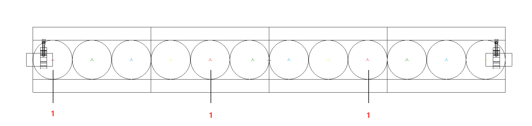
This four-cell strip light contains 12 light emitters. Each emitter has a color-coded 3D locus point. The red locus points are assigned a Light Emitter value of 1. These three emitters will be controlled by cell#1 to shine red light.
To attach the Parts record:
Select the container symbol, and select Modify > Edit Symbol.
Attach the Parts record to the 3D locus (rotation point) that you inserted when Creating the multi-cell container symbol definition:
In the Edit Symbol window, select the 3D locus.
Click the Data tab on the Object Info palette. Click Attach Record to open the Resource Selector, and double-click the Parts record to attach it.
Select Point from the record fields.
In the Edit Symbol window, place a 3D locus point for each emitter in the multi-cell device. Position each locus at the point of light emission. It's recommended that you color-code the locus by selecting a Pen color from the Attributes palette to indicate its light color.
Note that lighting devices with many emitters take longer to render.
Attach the Parts record to each 3D locus (light emitter) to define its controller cell:
In the Edit Symbol window, select the 3D locus.
Click the Data tab on the Object Info palette. Click Attach Record to open the Resource Selector, and double-click the Parts record to attach it.
In the Light Emitter field, enter the index number of the cell that will control the emitter’s light properties. Enter the same number for emitters that should shine the same light color. For example, enter 1 for each emitter that should use the color specified for cell #1.
If the Light Emitter value does not match the index number of a cell in the multi-cell device, an emitter is not created.
Click Exit Symbol at the upper right corner of the window to return to the drawing.
Attaching the Light Info Record to the container symbol
Attach the Light Info Record to the multi-cell container symbol, as described in Attaching the Light Info Record, but only fill in the global device data: 3D Symbol Name, Model Name, Inst Type, Weight (imperial and metric), Device Type, and FixtureID.
To attach additional records with default data to the multi-cell container symbol, see Spotlight preferences: Lighting Devices: Parameters pane.
All data from the Light Info Record, and any additional records, that are attached to the cell symbols or container symbol are transferred to the parameters of the multi-cell lighting device.
Once the multi-cell symbol definition is complete, use the Lighting Device tool to insert a multi-cell symbol instance in the drawing.