Marionette networks
A network is a series of nodes connected to create a functional script, executing commands as defined by the nodes. A completed network is considered a Marionette script. All scripts read from left to right, and the data flows in one direction. Networks can only be created and edited when in Top/Plan view.
Creating a network
To create a network:
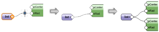
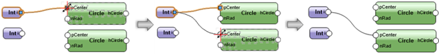
Using the Selection tool, click the control point on a node's port (output or input); then, move the cursor and click on another node's port.
Ensure that the Disabled Interactive Scaling mode of the Selection tool is disabled (turned off).
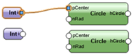
The two ports are connected by a wire. The outputs from any given node can be connected to multiple inputs on other nodes; likewise, multiple outputs can be connected to a single input node.
To neaten up a complex network, use the Align/Distribute commands to arrange the nodes; the wiring is not affected. (See Aligning and distributing objects.)
Naming nodes
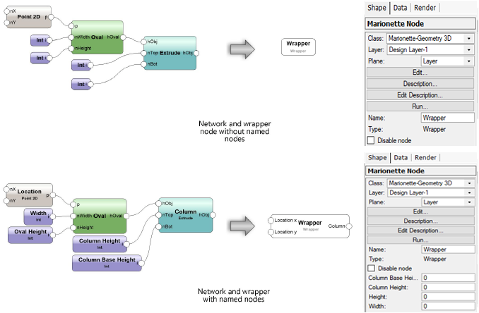
Naming nodes is an important part of creating and organizing a network, and impacts wrapper nodes significantly; for more information, see Marionette Wrapper nodes. Name input nodes and the nodes they are attached to in order to easily remember individual stages of more complicated networks. To name a node, select the node and enter a Name in the Object Info palette.
Named input nodes appear as fields on the Object Info palette of wrapper nodes; name them to quickly recognize and adjust values without having to edit the actual wrapper node.
The named inputs display in alphabetical order on the wrapper node.
The unused ports of named nodes display on wrapper nodes for easy connection to other networks. This is another good reason to name nodes.
Editing a network
To edit a network by changing the connections between nodes:
Select a node or wire to change. If you select the wire, the connected node closer to the beginning of the network is automatically selected. Because the wire can be disconnected only from the node that is not selected, you may need to select the other node to change the wire as needed.
Select the control point in the port to disconnect and move the control point; a preview displays.
Click on the port to connect. The wire is moved.
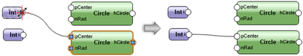
The wire can be disconnected only from the node that is not selected.
Alternatively, to remove the wire from the network, select the control point and then click in a blank area of the drawing.
All the wires connected to an output port can be moved to a different output port, or all removed from the network, in a single operation.
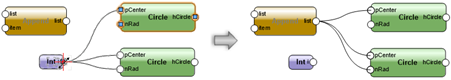
To move all wires connected to a port at once:
Select one of the nodes receiving input from the port to be moved.
Press and hold the Ctrl key (Windows) or Cmd key (Mac).
With the key still pressed, select the control point in the port to disconnect and move the control point; a preview of all connected wires displays.
Click on the port to connect and then release the key.
Alternatively, click in a blank area of the drawing to delete the wires.
If there are already wires connected to the destination output port, the Wire Rerouting Options dialog box opens. Select whether to add new wires to the existing wires connected to the port, or to remove the existing wires and replace them with the new wires.
The wires are moved.
Press and hold the Ctrl key (Windows) or Cmd key (Mac) throughout the operation to move all the wires connected to one output port to another output port.
If a node is deleted, all associated wires are also deleted.
Running a Marionette script
|
Command |
Path |
|
Run Marionette Script |
Context menu |
To run the Marionette script, right-click on any node in the network and select the command. Alternatively, select Run from the Object Info palette.
If an error occurs when running the script, an Execution Error dialog box opens, providing information about the type of error and its location in the script.
A Marionette preference determines which object remains selected after the script executes. You can choose to select the current node or select the objects created by the script. See Inserting a node with the Marionette tool for more information.
Objects created by running the script are grouped when the script completes execution. Running a script consecutive times replaces grouped objects created from the previous execution of the script; to retain the objects, rename the group or ungroup the objects.
Debugging a Marionette script
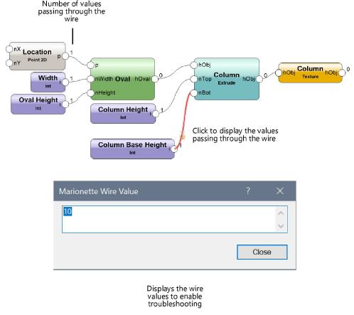
Use the Debug mode of the Marionette tool to troubleshoot networks when they are not functioning as desired. You can debug an unwrapped script, or double-click a wrapper node or object node to debug its underlying script. In debug mode, a number appears next to each output port, representing the number of values traveling from that output port to any attached input ports. Clicking on a wire opens the Marionette Wire Value dialog box, displaying the values that travel through the wire. The script executes upon closing the dialog box.
To avoid executing the script every time you click a wire, click Preferences on the Tool bar, and select Cache last run in debug mode. This option displays the wire values without re-executing the script.
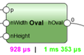
When Show execution time (Debug mode only) is selected in the Marionette Preferences dialog box, text under each node in the network displays how long it took the node to execute when the script ran. All nodes that are not input-only nodes also display the total execution time elapsed since the beginning of the network.