 Creating a pad or pad with retaining edge
|
Mode |
Tool |
Tool set |
|
Pad
Pad with Retaining Edge
|
Site Modifiers
|
Site Planning |

A pad is a 3D polygon representing the shape of an element which is to be added to, and normally modifies, the site model.
A pad with a retaining edge is similar to a regular pad site modifier, but it includes an additional configuration that defines an edge around the pad, allowing the terrain to be shaped around the pad. For example, the retaining edge can be used to adjust the terrain around a hardscape, offering precise control over the cut and fill amounts.
The modifier can be applied to the existing or proposed site model; the site model is modified when the site model is updated. Draw a pad with the Site Modifiers tool, or draw a polyline and then select the Create Objects from Shapes command to change it to a pad or pad with retaining edge object (see Creating objects from shapes).
To create a pad or pad with retaining edge:
Click the tool and mode. Specify the pad elevation from the Tool bar if desired.
Draw the pad object. Pads can be drawn closed or open (open pads are sometimes called “break lines”).
If the pad is sloping, specify the slope properties in the Object Info palette and/or by adjusting slope indicator control points and reshaping the modifier corners.
Select the method of defining the slope from the Slope Def list in the Object Info palette, and specify the slope parameters. The slope parameters do not display for a Slope Def of None. As values are entered in the Object Info palette, the other parameters are automatically calculated and displayed.
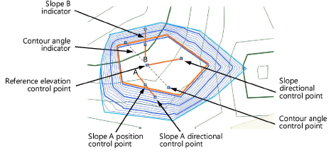
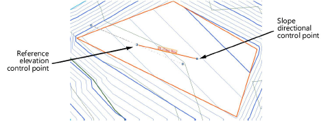
A banked slope can be contoured. The reference elevation control point indicates the start elevation of the site modifier, and the dashed line that passes through the reference elevation control point represents a constant elevation along the line. The dashed line indicates and controls the Contour Angle in the Object Info palette; it is only visible when the modifier is selected with the Selection tool, and it does not print. All the points on the line are at the same elevation; move the contour angle control points to define how the site modifier is banked along the pad slope. The contour angle must always be between 1 and 90 degrees of the slope vector (the banked contour cannot be parallel or perpendicular to the pad slope).
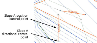
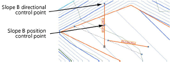
In addition to the pad slope, up to two custom slope axes can be specified: Slope A and Slope B. Slope arrows can be displayed on the pad to indicate the slope angles of the main slope and the two custom axes; select Show Slope, Show Slope A, and/or Show Slope B. The slope arrows are interactive; move a control point to adjust the slope direction, and the slope at that location is displayed. The control points of the slope arrows are only visible when the modifier is selected with the Selection tool, and they do not print.
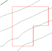
The Object Info palette displays the Elevation at End so that pads that meet at the bottom of a slope can be set to the same ending elevation. The planes for two site modifiers match when their contour lines are parallel, and the starting point of one modifier is on the plane of the other modifier.
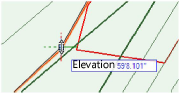
In Top/Plan view, select the control points of the slope arrows or the contour angle indicator, to interactively display the slope at that location. Changes to the slope values in the Object Info palette affect all the slope parameters. To set the slope plane, change the slope and the contour angle, or change slope A and slope B.
In Top/Plan view, the Reshape tool changes the shape of the pad. In a 3D view, use the Reshape tool to adjust the elevation at the corners of the site modifier. This changes the bank of the plane and modifies the contour angle and possibly other corners of the modifier, but does not modify the slope value. This interactive adjustment makes it easier to match two site modifiers so they meet at the same elevation.
Normally, create grade limits around the pad. The pad parameters can be edited from the Object Info palette.
The Site Modifiers tool generates a 3D pad polygon modifier that is always planar.
Click to show/hide the parameters.Click to show/hide the parameters.
|
Parameter |
Description |
|
Simplification Tolerance |
Enter a positive value to redefine the horizontal distance between the closest parts of two neighboring portions of the modifier. A longer distance simplifies the modifier polygon, reducing the number of source points that modify the site model. A shorter distance increases the number of source points that modify the site model. A value of 0 (zero) does not simplify the modifier. |
|
Modifier Vertex Count |
Displays the number of vertices created by the site modifier to modify the site model |
|
Config |
Indicates the type of modifier object |
|
Elevation |
Sets the elevation of the pad at its reference elevation control point |
|
Slope Def |
Select the method of defining the slope, or select None for a flat pad. After selecting the method, specify the Slope, the Elevation at End of the slope, or the Contour Angle, and the other values are automatically calculated and displayed. |
|
Slope |
Determines the slope of the modifier according to the selected slope definition method; enter the angle, percentage, or rise:run ratio |
|
Elevation at End |
Determines the slope by specifying the elevation of the modifier at the end of the slope; enter the elevation |
|
Contour Angle |
Defines how the site modifier is banked along the slope vector |
|
Apply To |
Specifies whether the site modifier applies to the existing or proposed site model |
|
Show Slope |
Displays a modifiable slope arrow and the current slope in Top/Plan view; Show Slope only displays if the slope is a value other than zero. The slope displays interactively by moving one of the control points.
|
|
Show Slope A |
Displays the slope A arrow and slope parameter. The slope displays interactively by moving one of the control points.
|
|
Show Slope B |
Displays the slope B arrow and slope parameter. The slope displays interactively by moving one of the control points.
|
|
Constrain Slope A/B Downward |
Forces the A and/or B slope to fall towards a lower elevation |
|
Update Calculations |
Updates the area and volume calculations displayed in the Object Info palette for the area of the site model located under the site modifier (grade limits must exist around the pad) |
|
Site model area and volume data |
Displays the area and volume information for the site model area located under the site modifier; select the units for the area and volume (grade limits must exist around the pad). For more information, see Site model properties. |
|
Vertex parameters |
Edits the path vertices; see Editing vertex-based objects |
|
Move (Pad with retaining edge only) |
Select the portion of the retaining edge modifier to edit (vertex or edge), and then edit its Z value, or scroll through its vertices with the left and right arrows and change the selected vertex Z value |
|
Edit |
For vertex selection made in Move, scrolls through the vertices, highlighting the currently selected vertex. Click the center button to highlight the selected vertex. |
|
Z (Pad with retaining edge only) |
Sets the elevation of the modifier item selected in Move or the vertex selected in Edit |
For a pad with retaining edge, the retaining edge modifier is drawn separately, and it can be used to control the depression around the pad. Reshape the retaining edge either from the Object Info palette or with the Reshape tool.
The Object Info palette vertex parameters include the ability to edit the Z value of the selected retaining modifier vertex or retaining modifier edge.
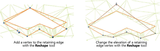
The retaining edge site modifier can be reshaped with the Reshape tool, similar to reshaping walls (see Reshaping walls). Move vertices, and add or delete vertices to reshape the retaining edge.
The Send to Surface command can be used to send either the retaining modifier edge or the pad to the surface of the site model.
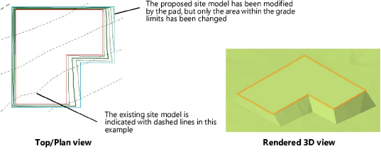
To reflect the pad modification, select the site model and click Update from the Object Info palette.
For predictable results, pads should not overlap. All pads should be either completely inside or completely outside of all grade limits. Pads, including those that may be incorporated into plug-in objects (such as landscape walls) cannot cross outside the grade limits.
