 Property line parameters
Property line preferences can be set before the property line object is inserted in the drawing in the object properties dialog box; access it by clicking the Property Line tool and then clicking the Preferences button from the Tool bar. These preferences serve as the new default for property lines inserted in the drawing until the preferences are changed.
Parameters can be edited for selected property line objects after placement, in the Object Info palette.
Edit the shape of selected property lines by using the Reshape tool, or by clicking the Edit with Dialog button from the Object Info palette. See Reshaping objects for information on using the Reshape tool for editing.
Click to show/hide the parameters.Click to show/hide the parameters.
|
Parameter |
Description |
|
Rotation |
Specifies the number of degrees to rotate the object (0.00 is horizontal) |
|
Name |
Enter a property line name |
|
Number |
Enter a property line number |
|
Simple Dialog on Bearing and Distance Mode (object properties dialog box only) |
For Bearing and Distance mode, displays the Create Property Line dialog box for simpler, linear-only property line data entry rather than the more comprehensive Define Property Line dialog box |
|
Tag |
If the tag is positioned outside the property line perimeter, a leader line displays |
|
Show Name |
Displays the property line name |
|
Show Number |
Displays the property line number |
|
Show Area |
Displays the area of the property line |
|
Name/Number/Area Text Style |
Select a text style from a library or the current file. To use the style defined for the object’s class, select <Class Text Style>. To format the text using options on the Text menu, select <Un-Styled>. See Using text styles and Formatting text. |
|
Fill Behind Text |
Displays a fill behind text |
|
Text Rotation |
Specifies the text rotation degrees |
|
Area Units |
Select the units in which to display the property line measurements; if Document Units is selected, the display follows the document’s display and dimensions settings |
|
Decimals |
Indicates the number of decimal places to display for the property line area |
|
Show Unit |
Displays the area units on the property line tags |
|
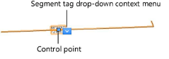
The segment label settings are global, and turn on/off the display of all segment labels of each kind (distance, angle, and curve) as a group. Hide or show individual segment labels with the Hide or Show drop-down context menu commands. Move individual segment labels using control points.
|
|
|
Edit with Dialog (Object Info palette only) |
Click to display the Define Property Line dialog box for editing the property line; see Creating property lines with bearing and distance data for information on parameters |
|
Annotate Segments |
Allows annotation of each segment of the property line; if this is deselected, the distance, angle and corner segment labels do not display, regardless of the individual reporting settings |
|
Reverse Direction |
Reverses the direction of the reported bearing information |
|
Corner Indicator |
Select the shape to draw at the corners of the property line |
|
Corner Indicator Size |
Specify the size of the corner indicator, in document units |
|
Report Distance |
If Annotate Segments is selected, specify whether and where to display the segment distance labels |
|
Report Angle |
If Annotate Segments is selected, specify whether and where to display the angle labels; if displayed at the corner, the text is rotated at the bisector angle |
|
Angle Format |
Select whether the annotations display in Azimuth or Bearing angle format |
|
Report Curve |
If Annotate Segments is selected, select whether and in what format to display the curvature information labels. If displayed on the segment, the information displayed is arc length (A) and radius (R); if displayed in a table on the drawing, the information includes location, delta, chord, tangent, length, and radius. |
|
Text Style |
Select a text style from a library or the current file. To use the style defined for the object’s class, select <Class Text Style>. To format the text using options on the Text menu, select <Un-Styled>. See Using text styles and Formatting text. |
|
Fill Behind Text |
Displays a fill behind text |
|
Segment Units |
Select the units in which to display the segment measurements; if Document Units is selected, the display follows the document’s display and dimensions settings |
|
Decimals |
If Document Units is not selected, indicates the number of decimal places to display for the segment labels |
|
Show Unit |
If Document Units is not selected, displays the units on the segment labels |
|
Site Model |
|
|
Site Modifier |
Select whether the property line is a site modifier and of what kind (see Creating grade limits and Creating a texture bed) |
|
Texture Bed Class |
If Texture Bed is selected, specify the texture bed class |
|
Info |
|
|
Surface Perim |
Displays the perimeter of the property line on the underlying site model; if there is no site model under the property line, the perimeter is calculated for a flat surface |
|
Surface Area |
Displays the area of the site model under the property line; if there is no site model under the property line, the area is calculated for a flat surface |
|
Vertex parameters (Object Info palette only) |
Edits the property line path vertices; see Editing vertex-based objects |
If the property line is designated to be a texture bed on the site model, select Tools > Organization. On the Classes tab, select the class designated as the texture bed class, and assign it a distinctive fill color or a texture. Select the site model and click Update from the Object Info palette; the property line displays as a texture bed on the site model. Switch to a 3D view and render for the full effect.
