 Simple beam
|
Command |
Workspace: Path |
|
Simple Beam |
Architect: AEC > Machine Design Landmark: Landmark > Machine Design Spotlight: Spotlight > Machine Design |
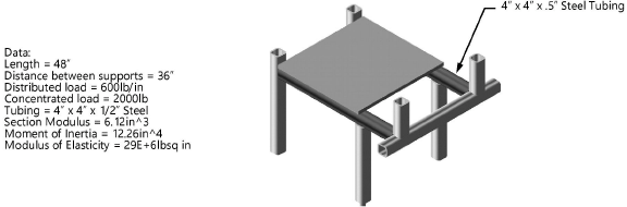
This example shows how the Simple Beam commands can be used to find the stresses on the horizontal elements of a certain machine part.
To calculate the stresses:
Select File > New.
The Create Document dialog box opens.
Select Use document template, and choose the Simple Beam (Imperial) or Simple Beam (Metric).sta template.
For version 2019 and later, the required .sta files are located in the [Vectorworks]\Libraries\Objects - Miscellaneous_Entourage\Machine Design\Templates folder. Copy the template file you need into your [User]\Libraries\Defaults\Templates folder.
Select the command.
The Simple Beam dialog box opens.
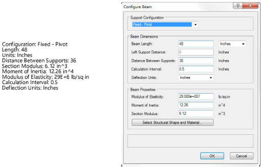
Click Configure Beam.
The Configure Beam dialog box opens.
Specify the beam properties. In this example, enter the following values:
To obtain the section modulus and moment of inertia of the tubing, select a tubing shape from the Resource Manager and place an instance of it on the drawing. Convert the tubing to a group and then use the Engineering Properties command to obtain the properties. See Obtaining engineering properties.
Click OK to close the Beam Properties dialog box.
Click Define Loads on the Simple Beam dialog box.
The Define Loads dialog box opens.
Specify the load properties. In this example, use the following values:
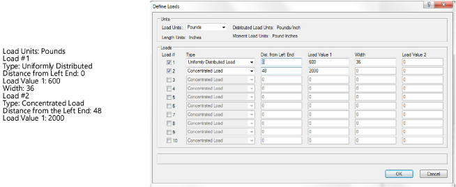
Click OK close the Define Loads dialog box.
In the Simple Beam dialog box, click Calculate Reactions, and then click Calculate Stresses and Deflection, and then click OK.
A simple beam diagram is created based on the information provided. See Simple beam analysis for more information on what is depicted in the diagram.
