Inserting house rigging points
|
Tool |
Tool set |
|
House Rigging Point
|
Rigging |
House rigging points are defined early in the design process. They represent the fixed points in a venue where trusses, hoists, mother grids, and bridles can be inserted. Use the House Rigging Point tool to place house rigging points in the drawing.
Bridles can also snap to structural members, if the option to Use Structural Member as House Rigging Point is enabled from the Bridle preferences.

|
Mode |
Description |
|
Symbol |
Opens a Resource Selector to select the house rigging point symbol; double-click a resource to activate it |
|
Trim Height |
Enter the Z height of the house rigging point |
|
Preferences
|
Set the default parameters for house rigging points |

To insert a house rigging point:
Click the tool.
Click Preferences to open the object properties dialog box and specify the tool’s default parameters. The parameters can be edited later from the Object Info palette.
Click Symbol on the Tool bar to select a resource from the Resource Selector.
Enter the Trim Height of the house rigging point on the Tool bar.
Click to place the object in the drawing.
You can insert multiple house rigging points at once. To insert a house rigging point on several selected objects, see Inserting house rigging points automatically. To duplicate house rigging points, use the Duplicate Array and Duplicate Along Path commands; see Duplicate array and Duplicating objects along a path.
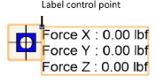
The house rigging point is inserted in the drawing, with a display of the forces in an associated label.
Click and drag the label control point to move the displayed forces. Select Text > Size to resize the text if needed.
Specify the Allowable Force X/Y/Z values on the Object Info palette to set the load limits of the rigging point.
Click to show/hide the parameters.Click to show/hide the parameters.
|
Parameter |
Description |
|
Properties |
|
|
Name |
Enter a name for the house rigging point, for informational and reporting purposes |
|
ID |
Enter a unique ID for the house rigging point, for use in reports |
|
Basket |
|
|
Basket |
Select the object that the basket wraps around, or select a <Custom> option. Any bridles inserted on the house rigging point use the selected basket type. The Basket type and dimensions can be changed for selected bridles by Adjusting the bridle configuration. |
|
Height/Width |
Displays the dimensions of the structural element that the basket wraps around. If <Custom Rectangle> is selected, enter the dimension values. |
|
Diameter |
Displays the diameter of the structural element that the basket wraps around. If <Custom Round> is selected, enter the diameter value. |
|
Structural Information |
|
|
Allowable Force X/Y/Z |
Specify the maximum forces that the house rigging point can support in the X, Y, and Z directions |
|
Force X/Y/Z |
Displays the forces applied to the house rigging point in the X, Y, and Z directions (Braceworks required for calculated values). The global coordinate system is used by default. To define the element coordinate system, see below. |
|
Display |
|
|
Symbol |
Displays the name of the house rigging point symbol |
|
Use Symbol |
Uses the specified house rigging point Symbol. Deselect the check box to use a circular schematic representation instead. |
|
Change Symbol |
Opens the Resource Manager to select a different symbol for the house rigging point |
|
Activates a one-click tool to define the orientation of the forces applied to the house rigging point; see below |
|
|
Classes |
Opens the Classes dialog box, to specify class naming for various parts of the house rigging point object. This allows the geometry and the label to be set to visible, grayed, or invisible. Use the standard class, select a class from the list of classes present in the drawing, or create a new class. Class Prefix: Specifies an optional default root class naming standard for all house rigging point elements; click Assign Default Classes With Prefix to begin all house rigging point class names with the prefix so they are sorted together. Use Standard Classes: Sets the class name for all house rigging point elements to the standard. Geometry: Specifies the class name standard for the house rigging point geometry; the class names shown here are applied to the geometry. Label: Specifies the class name standard for the house rigging point label; the class names shown here are applied to the labels. |
|
Reference Point |
|
|
Reference Point |
Select the drawing origin to use as a location reference, or use a hoist origin as the reference |
|
X/Y |
Displays the X and Y coordinates of the house rigging point relative to the selected origin |
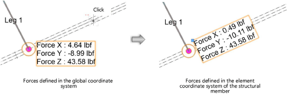
Defining the Element Coordinate System
For structural engineering purposes, you can define the element coordinate system of a house rigging point. For example, rotate the Force X/Y/Z values for alignment to a structural member.
To define the element coordinate system:
Select one or more house rigging points.
Click Define ECS on the Object Info palette.
Click in the drawing to define the force orientation. For example, click on the centerline of a beam to define the forces in the beam direction.
Alternatively, use the Rotate tool to change the force orientation, or set the Rotation from the Object Info palette.
The forces are oriented in the specified direction. To calculate the forces, see Performing calculations (Braceworks required). If the forces were calculated previously, the calculation results automatically adjust to the new orientation.