 Inserting a straight truss
|
Mode |
Tool |
Workspace: Tool set |
|
Modes for Creating single lines |
Straight Truss
|
Design Suite: Detailing Spotlight: Rigging |
Insert and configure straight trusses with the Straight Truss tool. Straight trusses function as rigging objects, so lighting devices and other loads can attach directly to the truss. Straight trusses support full 3D rotation, and they can be used to create schematic views.
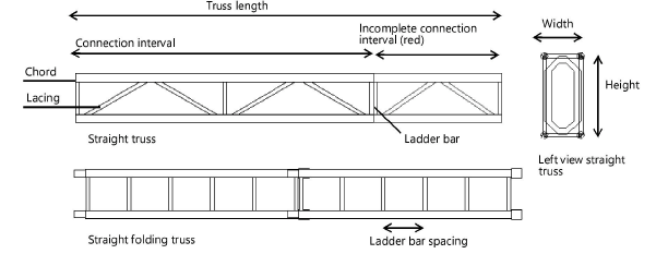
Straight truss parameters are illustrated by the following diagram.
To add a straight truss to the light plot:
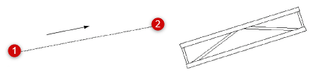
Click the tool.
Click to place the object in the drawing, and click again to set the length and rotation.
The first time you use the tool in a file, a properties dialog box opens. Set the default parameters. The parameters can be edited later from the Object Info palette.
Trusses are 2D/3D hybrid objects. Complex trusses can increase the time required to render the model in 3D.
Click to show/hide the parameters.Click to show/hide the parameters.
|
Parameter |
Description |
|
Roll Angle |
Rotates the truss on its X axis; the truss rotates around its insertion point |
|
Hanging Angle |
Rotates the truss on its Y axis; the truss rotates around its insertion point. When this angle is adjusted, the truss may appear shorter in Top/Plan view, and attached loads may appear to overlap. |
|
Rotation |
Rotates the truss on its Z axis; the truss rotates around its insertion point |
|
Position Name |
Enter a name for identification and reporting purposes. When the truss is used as a hanging position, this name automatically populates the Position field of any attached load objects. |
|
Index |
Specifies a unique identifier for the truss, which is combined with the Name for identification and reporting purposes |
|
Length |
Specifies the length of the truss in drawing units |
|
Cross Section |
Displays the associated cross section information for Braceworks structures |
|
Truss Cross Section |
Displays the cross section unique ID number, when a cross section file has been associated with the truss as described in Specifying cross section data. Cross section information is required for valid calculations; if there is no identified cross section, calculations will not be complete. |
|
Profile |
Select the truss profile from the list |
|
Connection |
Select the type of connection from the list |
|
Connection Interval |
Indicates the distance for dividing the truss into component sections |
|
Folding |
Indicates a folding truss |
|
Pre Rigged |
Select whether to include a light bar |
|
Height/Width |
Shows height and width values for the truss |
|
Chord Profile |
Select round or square chord tubing |
|
Chord Width |
Shows the diameter of round chords or the width of square chords |
|
Ladder Bar Spacing |
Specifies the interval of the ladder bars |
|
Ladder Bar Profile |
Select round or square ladder bar tubing |
|
Top/Side Ladder Bar Diameter |
Indicates the diameter of the top and side ladder bar tubing; enter 0 to draw no ladder bar |
|
Lacing Profile |
Select round or square lacing tubing |
|
Top/Side Lacing Diameter |
Indicates the diameter of the top and side lacing tubing. Enter 0 (zero) to draw no lacing. |
|
Distributed Weight |
Specifies the weight of the truss along the length of the truss |
|
Show 3D Detail |
Renders the truss with greater 3D detail |
|
Show Direction |
Places a directional indicator on the truss |
|
Highlight |
Displays odd sized truss divisions in red |
|
Message |
Provides information about the truss placement and indicates successful placement |
|
Select Truss System |
Selects the current truss and any other connected structural elements in the system |
|
Convert to Hanging Position |
Selects the entire system, including the truss and any connected rigging objects, for conversion to one or more hanging positions. Any attached loads are associated with the created hanging position(s); see Creating a hanging position object. |
A connection interval shorter than the defined interval length is displayed in red when Highlight is selected.
