 Creating schematic views
|
Command |
Path |
|
Create Schematic View |
Spotlight > Visualization |
The Create Schematic View command creates dynamic 2D views of rigging objects and the attached loads. Create schematic views before or after you have finished designing in 3D. Schematic views are linked with the model, so applicable edits are transferred between the model objects and their schematic views; see Concept: Schematic views.
To create a schematic view:
Do one of the following:
To create a schematic view of a single rigging object, select the object.
To create individual schematic views of multiple rigging objects, select the objects.
To create a schematic view of a connected rigging system, select a rigging object in the system.
Select the command.
The Create Schematic View dialog box opens; select the layer and view.
Click to show/hide the parameters.Click to show/hide the parameters.
|
Parameter |
Description |
|
Layer |
Select an existing design layer, or create a new one, for the schematic view. For organizational purposes, place the schematic views on a different design layer than the model objects. |
|
View |
Select the 2D component view to show in the schematic view; see Concept: 2D components for symbol definitions and plug-in objects |
|
Create a schematic view of the rigging system |
Uses the selected rigging object to identify the connected rigging system, and creates a schematic view of the entire system |
To create a schematic view of a connected rigging system, select Create a schematic view of the rigging system. Otherwise, proceed to step 4.
Click in the drawing to place the schematic view.
For a single rigging object, the rigging object is placed at the click point.
For multiple rigging objects, the first rigging object in the stacking order is placed at the click point. Click to place each rigging object individually.
For a connected rigging system, the rigging object that was selected to create the schematic view is placed at the click point with the system objects connected to it.
The schematic objects are inserted in the active class.
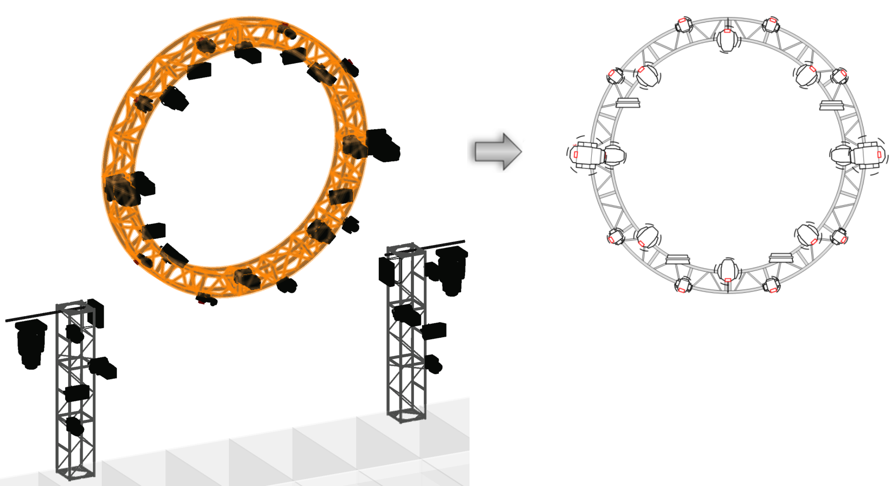
A schematic Top view is created from the circular truss system
If the schematic rigging objects overlap in the selected View, they are placed on top of each other according to the stacking order.
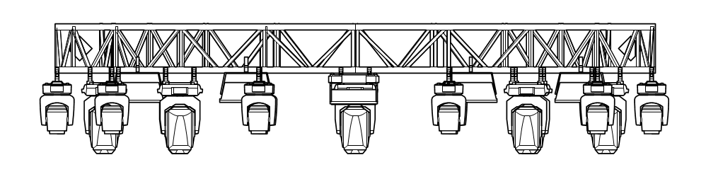
In a schematic Front view of the circular truss system, the overlapping trusses are placed on top of each other for a realistic appearance
In most cases, the layout and orientation of objects in the schematic view match the 3D model. Some exceptions are made for visibility reasons. If a connected rigging system cannot be shown in the schematic view, each rigging object in the system will be placed individually. If a load is rotated at a different angle from its rigging object, the orientation of the schematic load may not match the model.
In the schematic view, lighting devices and other load objects can be added, removed, and repositioned; see Managing loads for more information.
