 Adding roof elements to roof objects and roof faces
Once a roof object or a roof face has been created, dormer windows and skylights can be added.
Creating dormer windows

You can create a wide variety of dormer windows in roof objects and roof faces. A dormer can be set to the same style as the roof, to create a uniform appearance.
Dormer walls are always drawn in a clockwise direction for easy texture application.
To create a gable dormer window in a roof object or roof face:
From the Resource Manager, right-click on a window resource and select Make Active from the context menu. The Symbol Insertion tool is automatically activated from the Basic palette.
The window must be a symbol, not a plug-in object.
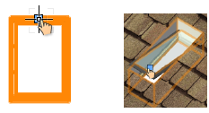
Switch to Top/Plan view.
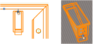
Click to place the symbol in the roof object or roof face. The Edit Roof Element dialog box opens.
From the right side of the dialog box, click Edit dormer, and then select the dormer style (trapezium, gable, shed, hip, or bat).
The parameters automatically change according to the selected dormer style, with values for placing the dormer at the location specified with the mouse click.
Click to show/hide the parameters.Click to show/hide the parameters.
|
Parameter |
Dormer Style |
Description |
|
Center vertically |
All |
Places the center of the window symbol in the center of the available vertical space in the front face of the dormer; the normal insertion point is not used |
|
Offset from top |
All |
Locates the top of the window symbol a set distance from the top of the dormer face; the normal insertion point is not used |
|
Height offset |
All |
Indicates the vertical distance from the top of the point of engagement with the roof, or where the roof and the dormer meet, to the bearing point, which is usually along the top of the bearing wall |
|
Building line offset |
All |
Specifies the distance from the building outline to the plan center of the window symbol |
|
Offset from corner |
All |
Sets the distance from the corner of the roof to the center of the dormer; the roof corner that the measurement is taken from is always to the left of the dormer when facing it |
|
Top width |
Trapezium, Bat |
Determines the width of the top roof and sets the front face’s trapezoid shape; the front face is always symmetrical when using this option |
|
Right slope |
Trapezium, Gable, Hip |
Determines the angle of the right edge of the front face; the front face can be asymmetrical when using this option |
|
Left slope |
Trapezium, Gable, Hip |
Specifies the angle of the left edge of the front face. Along with the Right slope, this dimension determines the top width of the front face. Right slope must be selected for this option to be available. |
|
Bottom width |
Trapezium, Gable, Bat |
Sets the width of the bottom edge of the front face; works in conjunction with either the Top width or the Left and Right slope entries and is required |
|
Slope |
Trapezium, Shed, Bat |
Indicates the angle of the pitch of the top dormer roof as measured from a horizontal line |
|
Width |
Gable, Shed, Hip |
Horizontal distance of the front face of the dormer |
|
Front slope |
Hip |
Indicates the angle of the pitch of the front face of the dormer roof as measured from a vertical line |
|
Height |
All |
Specifies the elevation height of the front face of the dormer; determines the plan depth of the dormer |
|
Top width |
Bat |
Indicates the width of the top of the roof as measured along the front face of the dormer |
|
Bottom Height |
Bat |
Distance from the bottom of the dormer to the beginning of the compound curves of the roof as measured along the front face of the dormer |
|
Depth |
All |
Sets the plan distance from the point of engagement with the roof to the front face of the dormer; determines the elevation height of the front face of the dormer |
|
Overhang |
Gable, Shed, Hip |
Amount of roof extension past the dormer’s front roof face |
|
Control Point |
Bat |
Point where the two curves of the roof meet. This option controls the location of that point from the side edge of the dormer as measured along the roof. The location of this point determines the depth of the curves that make up the roofline. |
The dormer with window is created and placed according to the parameters specified. A hole is automatically created in the roof where the dormer walls exist.
Editing dormer windows
To edit a dormer window:
Select the roof or roof face.
Selection handles display around the roof or roof face and at the location of each dormer and skylight.
Position the cursor over the selection handle for the dormer and click.
The Edit Roof Element dialog box opens, with the dormer parameters displayed.
Edit the parameters as described in Creating dormer windows.
To remove the dormer completely, select Remove object.
The Object Info palette of a selected roof with a dormer contains additional Dormer Settings parameters:
Wall Thickness and Roof Thickness: These thickness values apply only to the dormer.
Use Style For Dormer: If the roof itself has a roof style applied, select Use Style For Dormer to apply the same style to the dormer. The Roof Thickness of the dormer is then set by the components in the style, and cannot be edited from the Object Info palette.
Creating skylights
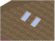
A full skylight, complete with a window symbol, can be placed in a roof object or roof face.
A 3D-only window symbol is required for creating a skylight. An existing hybrid symbol can be converted to a 3D symbol; place the symbol in the drawing and set its parameters, and then switch to a 3D view. Select the symbol, and then select Modify > Convert > Convert to Group. Select the Convert all sub-objects option in the Convert to Group Options dialog box. With the group selected, choose Modify > Create Symbol to create a 3D symbol from the group, and select the On Edge option for Insert in Walls.
When creating your own skylight symbols, set the insertion point of the symbol at the back and center of the symbol.
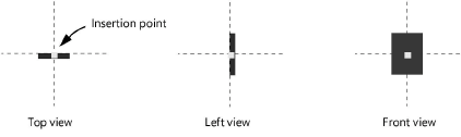
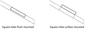
The insertion point of the symbol determines whether a skylight will be flush or surface-mounted.
To insert a skylight:
From the Resource Manager, right-click on a 3D symbol to use in the skylight, and select Make Active from the context menu. The Symbol Insertion tool is automatically activated from the Basic palette.
Hybrid and 2D window symbols will not work for skylights, though hybrid symbols can be used to create a cutout.
Switch to Top/Plan view.
Click to place the symbol in the desired location in the roof object or roof face. The Edit Roof Element dialog box opens.
From the right side of the dialog box, click Edit skylight to display the parameters that apply to skylights.
Click to show/hide the parameters.Click to show/hide the parameters.
|
Parameter |
Description |
|
Offset from corner |
Specifies the distance from the edge of the roof to the center of the skylight symbol |
|
Offset from building line |
Sets the distance from the edge of the building to the center of the skylight symbol |
|
Do not insert symbol |
Creates a cutout in the roof without inserting the window symbol |
|
Remove object |
Deletes the skylight from the roof |
|
Edit dormer |
Accesses the dormer parameters instead of the skylight parameters |
|
Hole Cut |
Select a hole cut type for this skylight. Vertical: Hole edges are perpendicular to the active layer plane. Splayed: The bottom edge of the hole is perpendicular to the active layer plane, and the top edge of the hole is parallel to the active layer plane. Square: Hole edges are perpendicular to the roof surface. |
Editing skylights
To edit a skylight:
Select the roof or roof face.
Selection handles display around the roof or roof face and at the location of each dormer and skylight.
Position the cursor over the selection handle for the skylight and click.
The Edit Roof Element dialog box opens, with the skylight parameters displayed.
Edit the parameters as described in Creating skylights.
To remove the skylight completely, select Remove object.