 Creating a spoil pile area
|
Mode |
Tool |
Tool set |
|
Spoil Pile |
Site Modifiers
|
Site Planning |


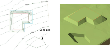
A spoil pile refers to an area where excess earth is used to help balance the cut and fill, so that the site does not require earth to be moved in or out. A spoil pile area applies an even thickness of cut or fill for the site. To create a spoil pile, either use the Site Modifiers tool, or draw a polyline and then select the Create Objects from Shapes command (see Creating objects from shapes).
To create a spoil pile area:
Create the site model and add any modifiers, such as pads and roads, and update the proposed site model by clicking Update from the Object Info palette of the selected site model.
The initial cut and fill volumes are displayed in the Object Info palette.
Click the tool and mode. Specify the elevation from the Tool bar if desired.
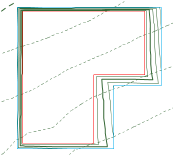
Draw the spoil pile area.
In the Object Info palette, adjust the elevation of the spoil pile up or down depending on whether fill is required or excess fill is present.
Click to show/hide the parameters.Click to show/hide the parameters.
|
Parameter |
Description |
|
Simplification Tolerance |
Enter a positive value to redefine the horizontal distance between the closest parts of two neighboring portions of the modifier. A longer distance simplifies the modifier polygon, reducing the number of source points that modify the site model. A shorter distance increases the number of source points that modify the site model. A value of 0 (zero) does not simplify the modifier. |
|
Modifier Vertex Count |
Displays the number of vertices created by the site modifier to modify the site model |
|
Apply To |
Specifies whether the site modifier applies to the existing or proposed site model |
|
Update Site Model |
Updates the site model with any site model modifications that have occurred. If the update causes the site model contours to fall outside the minimum/maximum elevation range specified in the model settings, an alert displays, allowing the range to be adjusted. |
|
Configuration |
Indicates the type of modifier object |
|
Show the surface in 3D |
In 3D views, represents the modifier with a 3D polygon. This is convenient when working with a modifier independently of a site model, or when it's helpful to view the site modifier on the surface of the site model in 3D views. Deselect the option to view only the effects of the modifier on the site model. |
|
Spoil Pile |
|
|
Elevation |
Sets the reference elevation of the spoil pile; a positive elevation is reported as fill volume, while a negative elevation is reported as cut volume, when calculating the underlying existing or proposed site model |
|
Information |
|
|
Update Calculations |
Updates the area and volume calculations displayed in the Object Info palette for the area of the site model located under the site modifier |
|
Site model area and volume data |
Displays the area and volume information for the site model area located under the site modifier; select the units for the area and volume |
|
Vertex parameters |
Edits the path vertices; see Editing vertex-based objects |
Select the site model and click Update from the Object Info palette.
With the site model still selected, click Update Cut and Fill Calculations from the Object Info palette.
Alternatively, click Update Site Model and then Update Calculations from the Object Info palette of the selected site modifier.
Evaluate the results of the spoil pile by checking the Net C&F Volume results in the Object Info palette of the selected site model. If the spoil pile elevation needs adjustment, select the spoil pile and enter a new Elevation value from the Object Info palette. Then select the site model, click Update, and then click Update Cut and Fill Calculations.
Continue adjusting the spoil pile elevation until a balanced cut and fill volume is achieved.
Display the 3D cut and fill volumes by selecting Cut and Fill as the 3D Display from the Object Info palette of a selected site model. The cut and fill colors are specified on the Site Model tab of the Graphic Properties dialog box. In addition, a 2D polygonal representation of the cut and fill area can be displayed by selecting 2D Cut & Fill Area from the Site Analysis tab.
