 Sculpting the site model surface
|
Tool |
Tool set |
|
Sculptor
|
Surface Sculpting |

The Sculptor tool performs a push/pull operation on a specific portion of the site model surface, in a vertical direction.

|
Mode |
Description |
|
Single Element Selection
|
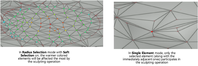
Selects a single TIN element (triangle, edge, or vertex) and its defining elements (the edges and vertices that make up the triangle, or vertices on either side of the edge) for sculpting. Immediately adjacent vertices and faces are also affected. |
|
Radius Selection
|
Selects an area for sculpting that is defined by the Radius value |
|
Radius |
Determines the extent of the effects on the site model surface when in Radius Selection mode |
|
Soft Selection (Radius Selection only)
|
Toggles whether soft selection is used for the sculpting operation. Soft selection affects vertices in the center of the operation the most, with a gradual falloff of the effect (according to the Falloff value), for a natural, rounded modeling operation. When Soft Selection is enabled, the amount of falloff, and therefore, the degree of the sculpting operation’s effect, is indicated by colored vertices. The closer the color is to red, the more effect the sculpting operation will have on that portion of the surface. As the colors move along the spectrum towards blue, this indicates that the elements are less fully selected, and will not move as much. When Soft Selection is disabled, all of the vertices within the radius are affected by the sculpting operation to the same degree, and all of the affected vertices display in red. |
|
Falloff |
Sets the degree of soft selection, from 0 – 100%. A higher value results in a more gentle falloff of the sculpting effect when Soft Selection is enabled. A lower value results in a sharper, more narrow area being affected. |
|
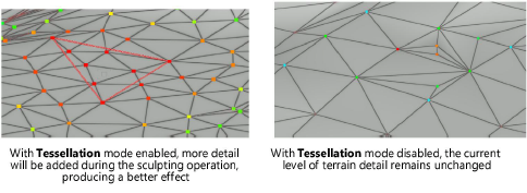
Tessellation (Radius Selection only)
|
Toggles whether tessellation is on or off. This effect automatically increases the number of vertices and therefore, the level of detail, as the site model is sculpted, according to the Max Distance value. More tessellation increases the number of created vertices and edges, allowing detailed sculpting to occur in areas where currently, a low level of detail exists.
|
|
Max Distance |
Specifies the amount of tessellation to use by setting the distance at which to insert vertices. Vertices are inserted until all edges in the affected area conform to the distance value; a higher relative distance value will add less tessellation, or amount of detail. Entering a short distance may slow down the sculpting operation and could impact the overall site model performance. |
To sculpt the site model surface:
In site model Surface sculpting mode, click the tool.
Select the desired mode depending on the site model conditions and the desired outcome.
Click Single Element Selection to only move a single selected vertex, edge, or face. Directly adjacent elements are also affected.
Click Radius Selection mode and specify a Radius to sculpt a larger area, affecting many elements at once.
In Radius Selection mode, toggle Soft Selection on or off depending on the degree to which elements within the radius should be affected, and set the Falloff value when it is enabled.
In Radius Selection mode, toggle Tessellation mode on to create additional vertices and edges as the sculpting occurs, and specify a Max Distance value when it is enabled.
As the cursor moves over the site model surface, its elements (vertices, edges, or faces) are highlighted. Click on a site model vertex, edge or face; the effect of the operation, and the radius in Radius Selection mode, varies slightly depending on which element is selected. Selecting an edge or face also selects its associated vertices, and the operation will affect the adjacent face sizes. The operation occurs only in a vertical direction.
Click to begin the sculpting operation, and drag to move the selected site model element up or down vertically. The cursor changes to a double-headed arrow. Move the cursor to expand or subtract from the surface of the terrain. The distance can also be specified by entering a positive or negative value in the Distance field in the floating Data bar. The results preview on the drawing; a black dot temporarily indicates the original starting point for reference.
Click to complete the sculpting operation.
The minimum and maximum contour elevations may need adjustment to accommodate the new site model shape; if so, an alert opens. Normally, you want all the contours to be visible, so click Yes.
