 Railing and fence settings
The settings are grouped into several panes of related parameters. Select each group of parameters from the list in the left pane of the dialog box; the parameters display in the center pane. The right pane of the dialog box always displays a preview of the object based on the current settings.
Railing/fence settings
Click to show/hide the parameters.Click to show/hide the parameters.
|
Parameter |
Description |
|
View |
Specifies the view for the object preview: select a standard view, or a 2 or 4 meter section in right isometric view |
|
Render Mode |
Specifies a render mode for the preview |
Railing/fence settings: General pane
Click to show/hide the parameters.Click to show/hide the parameters.
|
Parameter |
Description |
|
Symbol Selection |
Opens the Resource Selector to select an existing railing or fence symbol. When you edit settings in the dialog box, “Current Settings” displays, to indicate that the current settings haven’t been saved as a symbol. |
|
Save as Symbol |
Opens the Save Railing/Fence dialog box to save the current configuration for future use; see Saving a railing or fence as a symbol |
|
Component |
Specifies whether to create a 2D or 2D/3D hybrid object |
|
Class |
Specifies a class for the object to control appearance and visibility |
|
Offset |
Specifies an offset from the drawn path for the railing or fence object. Relative to the drawing direction, the object is offset to the left of the path for a positive number, or to the right for a negative number. |
If you select a different symbol after making parameter changes on any tab, the New Railing dialog box opens. Each railing or fence symbol has default settings. If you switch to a new symbol, you can either use the default settings, or transfer the current settings to the new object. From the dialog box, select specific settings to transfer, or click All or None to select or deselect all the settings.
Railing/fence settings: Top Rail pane
Click to show/hide the parameters.Click to show/hide the parameters.
|
Parameter |
Description |
|
Top rail |
Adds a top rail to the object |
|
Profile |
Specifies a profile shape for the top rail; also specify dimensions, if necessary. Round: Enter the Diameter. Rectangular: Enter the Width and Height. Octagon: Enter the Diameter. Custom Profile: Select a profile from the list of available shapes. You can create a 2D symbol to use as a custom profile. Save the profile in the current document, or in a file in your user folder: [User]\Libraries\Defaults\Railing Fence\Profile Top Rail. |
|
Height |
Calculated Height automatically calculates the rail height from the post height. Custom Height sets the height as specified. |
|
Top rail ends at post |
Specifies whether the top rail ends at the first and last post; when deselected, the rail length matches the length of the object’s path |
|
Extensions for Inclined Top Rail |
For railings or fences drawn with 3D Line mode, specifies lengths for the extensions of the top rail beyond the start and end of the object path. If the object is on an incline, also specify whether the extension continues the slope of the main rail, or is horizontal to the ground. |
Railing/fence settings: Post/Bracket pane
Click to show/hide the parameters.Click to show/hide the parameters.
|
Parameter |
Description |
|
Post option |
Specifies whether to use a Post, No Post, or Wall Bracket; the settings available on the pane change depending on the selection |
|
Post settings |
The following settings are available when the Post option is selected |
|
Display posts in 2D view |
Specifies whether posts are visible in Top/Plan view |
|
Post Height |
Calculated Height automatically calculates the rail height from the post height. Custom Height sets the height as specified. |
|
Profile |
Specifies a profile shape for the post; also specify the dimensions, if necessary. Round: Enter the Diameter. Rectangular: Enter the Width and Height. Octagon: Enter the Diameter. Custom Profile: Select a profile from the list of available shapes. Custom Symbol: Select a symbol from the list of available symbols. You can create a 2D symbol to use as a custom profile, or a 3D symbol to use for the post. Save the profile or post symbol in the current document, or in a file in the appropriate folder in your user folder: [User]\Libraries\Defaults\Railing Fence\Profile Posts or [User]\Libraries\Defaults\Railing Fence\Symbol Posts. |
|
Arrangement |
|
|
Place post at starting point |
Places a post at the specified distance from the start of the object path |
|
Place post at end point |
Places a post at the specified distance from the end of the object path |
|
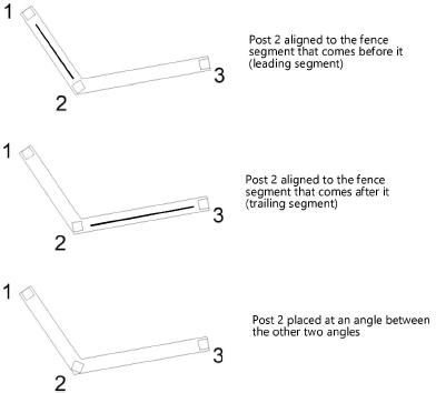
Place post at corner |
Places a post at each corner of the object path. Align Corner Post Angle to specifies how to align each corner post with the fence or railing:
|
|
Place two posts at corner |
Places a post at the specified distance before and after each corner of the object path |
|
Arrangement options |
Specifies the arrangement of the remaining posts along the fence or railing: Approximate Distance calculates a number of posts and distributes them evenly along the object path. Fixed Distance calculates a number of posts and positions them at the specified distance from each other along the object path; this may result in uneven spacing for the end posts. Number of Posts evenly distributes the specified number of posts along the object path. |
|
Position |
When an existing railing or fence is selected, opens the Position Post dialog box; see Editing post or bracket positions |
|
Use face mount for post |
Adds an L-shaped mounting bracket to the bottom of each post |
|
Orientation |
Specifies the direction of the bracket |
|
Height |
Specifies the height of the bracket |
|
Distance |
Specifies the horizontal length of the bracket |
|
Wall Bracket settings |
The following settings are available when the Wall Bracket option is selected |
|
Display posts in 2D view |
Specifies whether bracket posts are visible in Top/Plan view |
|
Display overhang in 2D view |
Specifies whether bracket extensions are visible in Top/Plan view |
|
Wall Bracket for Top Rail |
|
|
Wall Position |
Specifies the direction of the bracket extension |
|
Profile |
Specifies the profile shape of the bracket |
|
Diameter |
Specifies the diameter of the bracket extension |
|
Height |
Specifies the height of the bracket |
|
Clear Distance |
Specifies the distance between the bracket post and the wall |
|
Arrangement |
|
|
Place bracket at starting point |
Places a bracket at the specified distance from the start of the object path |
|
Place bracket at end point |
Places a bracket at the specified distance from the end of the object path |
|
Place two brackets at corner |
Places a bracket at the specified distance before and after each corner of the object path |
|
Arrangement options |
Specifies the arrangement of the remaining brackets along the fence or railing: Approximate Distance calculates a number of brackets and distributes them evenly along the object path. Fixed Distance calculates a number of brackets and positions them at the specified distance from each other along the object path; this may result in uneven spacing for the end brackets. Number of Brackets evenly distributes the specified number of brackets along the object path. |
|
Position |
When an existing railing or fence is selected, opens the Position Wall Bracket dialog box; see Editing post or bracket positions |
Editing post or bracket positions
You can edit the positions of specific posts or wall brackets in a selected railing or fence object.
To edit post or bracket positions:
Select an existing railing or fence object and click Settings from the Object Info palette. From the Post/Bracket pane of the Railing/Fence Settings dialog box, click Position.
Depending on the selected object, either the Position Post or Position Wall Bracket dialog box opens.
All current posts or brackets are listed, along with their current settings. Select an object from the list, and then click the appropriate button. The preview window updates as you edit the post or bracket positions.
Click to show/hide the buttons.Click to show/hide the buttons.
|
Button |
Description |
|
New |
Opens a dialog box to add a new post or bracket to the path, halfway between the selected object and the object beneath it in the list; enter offset information for the new object, if needed. Offset Position Max. and Offset Position Min. represent the end and beginning of the path, respectively. Offset Position is the distance to offset the post or bracket from its default, calculated position; a negative number moves the object toward the beginning of the path, and a positive number moves it toward the end of the path. Offset to Bottom is the distance to offset the bottom of the post from its default, calculated position; a negative number shortens the post, and a positive number lengthens it (for posts only). Align Corner Post Angle to specifies how to align each corner post with the fence or railing (for corner posts only). |
|
Edit |
Opens a dialog box to edit the offset information for the selected object |
|
Delete |
Deletes the selected object |
|
Default Settings |
Restores the defaults, discarding all additions, deletions, and offsets |
Railing/fence settings: Infill pane
These parameters are only available when the Post option has been selected on the Post/Bracket pane.
Click to show/hide the parameters.Click to show/hide the parameters.
|
Parameter |
Description |
|
Infill |
Adds infill between the posts |
|
Extend Infill to |
For railings or fences drawn with 3D Line mode, specifies the extent of the infill. First/Last post ends the infill at the first and last post. If the object is on an incline, Start/end of the path extends the infill to match the top rail extension; also specify whether to extend to the start of the object’s path, the end of the path, or both directions. |
|
Extend and miter infill at start |
For railings or fences drawn with 3D Line mode, select to align the infill to the top of the rail extension at the start of the object path |
|
Extend and miter infill at the end |
For railings or fences drawn with 3D Line mode, select to align the infill to the top of the rail extension at the end of the object path |
|
No infill at corner without post |
Specifies that no infill is created adjacent to corners without a post. When deselected, infill is created in corners with no posts. |
|
Infill Type |
Crossbars with Bars adds crossbars and bars between the posts Frame with Bars adds frames with bars between the posts Panel adds solid panels between the posts |
|
Create Members at |
Specifies whether to add members at the top, bottom, and sides of each section of railing or fence (crossbars and frames only) |
|
Clear Distance to Top Rail |
Specifies the distance between the top rail and the top of the infill |
|
Clear Distance to Floor |
Specifies the distance between the bottom of the infill and the floor |
|
Shape of Profile |
Specifies the profile shape for the members; also enter the dimensions, if necessary (crossbars and frames only). Line: No dimensions Flat: Enter the Width/Diameter of Profile Round: Enter the Width/Diameter of Profile Rectangular: Enter the Width/Diameter of Profile and Height of Profile |
|
Bars |
These settings apply to crossbar and frame infill types only |
|
Create Bars |
Specifies whether to add horizontal and vertical bars, and whether to rotate them |
|
Shape of Profile |
Specifies the profile shape for the bars; also enter the dimensions, if necessary. Line: No dimensions Flat: Enter the Width/Diameter of Profile Round: Enter the Width/Diameter of Profile Rectangular: Enter the Width/Diameter of Profile and Height of Profile |
|
Maximum Clear Distance |
Specifies the maximum distance between the bars |
Railing/fence settings: Miters pane
Enter an angle for miters at each end of the railing or fence; enter 0 (zero) for a straight edge.
Railing/fence settings: 2D and 3D Attributes panes
You can set both 2D and 3D attributes for rail and fence components. The panes work the same way for both sets of attributes.
Click to show/hide the parameters.Click to show/hide the parameters.
|
Parameter |
Description |
|
Attributes 2D or 3D |
Lists all geometry that has graphic attributes settings. The class and graphic attributes of each part of the object are displayed. Double-click a line to set attributes for the part; see The Attributes palette. 3D parts have material and texture options. If a material resource is used to define a part, the material typically provides the fill, texture, physical attributes, and construction information needed for drawings, renderings, and reports. To specify a material, select Use Material and select a material from the Resource Selector. The Fill and Texture settings are set to the material’s settings, and the Fill parameters are disabled. For Texture, select whether to use the class texture, to use the material’s texture, to select a different texture, or to use no texture. |
|
Make All Attributes by Class |
Sets all fill, pen, and texture attributes by class, except those that come from a material |
|
Remove All By Class Settings |
Removes all class settings for fill, pen, and texture attributes; does not affect material definitions with attributes set by class |
Saving a railing or fence as a symbol
You can save the railing or fence configuration as a symbol in the current file or in a library file. The object is saved as a red symbol and becomes a plug-in object with pre-set parameters when inserted. See Concept: Vectorworks symbols.
To save a railing or fence as a symbol:
From the Railing/Fence Settings dialog box, open the General pane, and click Save as Symbol.
The Save Railing/Fence dialog box opens.
Click to show/hide the parameters.Click to show/hide the parameters.
|
Parameter |
Description |
|
Destination |
Specify whether to save the symbol in the current file, or in a custom default library file located in the user folder; the exact location is displayed upon saving |
|
Name |
Enter a name for the symbol |
|
Symbol Folder |
If you’re saving the symbol in the current document, select the current file name to save the symbol at the top level, or double-click a folder from the list to save the symbol in that folder. To create a folder, click New Folder. To create a subfolder within a folder, select the folder and click Browse, or double-click the folder. |
Select the destination file for the symbol.
To save the symbol in a library file, select Save as template in library file and enter a name for the symbol. It will be available from the Resource Selector and Resource Manager, in the Railing Fence folder in your User Libraries. Library files can be shared among users.
To save the symbol in the current file, select Save as symbol in current document, enter a name for the symbol, and select a folder destination for it. It will be available from the Resource Selector and Resource Manager. Symbols can be shared by exporting them from the Resource Manager (see Exporting resources).
