 Framing a wall
|
Command |
Path |
|
Wall Framer |
AEC > Framing |
The Vectorworks Architect product creates a highly detailed estimate of the placement and number of studs needed to frame walls. In addition to showing stud placement in a framing diagram, the Wall Framer command also automatically generates frame elevation drawings and two different worksheets, Frame TakeOff and Frame Wall Info.
To use the wall framer:
Ensure that the walls have the desired height. If necessary, change the wall height.
Select the command.
If a framing model has not yet been created, the New Framing Model dialog box opens. Enter a name for the framing model design layer (up to eight characters).
Click Create.
The Wall Framing dialog box opens. Select the desired settings for the framing model.
Click to show/hide the parameters.Click to show/hide the parameters.
|
Parameter |
Description |
|
Model Name |
Select the framing model layer to be used |
|
New |
Opens the New Framing Model dialog box to create a new model |
|
Delete |
Deletes the currently selected model. Click Yes to delete the selected model. This operation cannot be undone. This command cannot be used if there is only one model in the document. |
|
Framer Output |
|
|
3D Model |
Creates a 3D model layer, complete with the placement of studs, top plates, sole plates, and other components required for framing |
|
2D Model |
Creates framing plan and framing diagram layers. The framing plan is a top view of the wall showing the sole plate and stud placement and is drawn in a layer that parallels the layers in the framing model. The top plates are removed to show the stud placement. The framing diagram is an elevation view showing the sole plate, top plates, and stud placement. The framing diagram is drawn in a new design layer and generates as many layers as needed. |
|
Worksheets |
Creates two sets of worksheets. The first set provides details on the framing results, including a list of studs sorted by layer, class, frame, and size (Frame TakeOff). The second set provides a summary of frame information, sorted similarly, but providing area and linear footages itemized for each framed wall (Frame Wall Info). |
|
Frame the following layers |
Select which layers contain wall data to frame |
|
Options |
Opens the Wall Class dialog box to allow the editing of wall class values; see step 4 |
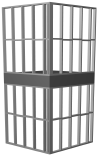
The framing diagram and the 3D model representations also include symbols and inserted items, such as doors and windows.
The Wall Class dialog box opens. Enter the framing parameters for each wall class.
Click to show/hide the parameters.Click to show/hide the parameters.
|
Parameter |
Description |
|
Wall Class |
|
|
Name |
Lists the classes that contain walls to be framed; walls in the classes in this list are included in the framing model. The framing parameters for each class are displayed beneath. |
|
New |
Click to add an additional wall class to the list to be framed |
|
Delete |
Deletes the currently selected wall class from the list to be framed. Click Yes to delete the selected class. This operation cannot be undone. |
|
Stud Spacing |
Enter the center-to-center distance between studs in this wall class |
|
Sheet Stock Width |
Enter the width of the wall sheathing; this is the horizontal sheathing dimension |
|
Max Plate Length |
Enter the length of lumber to be used for top and bottom frame members in this wall class |
|
Sheet Stock Height |
Enter the width of the wall sheathing; this is the vertical sheathing dimension |
|
Lumber |
|
|
Nominal |
Select the lumber type to use for this wall class; the default types are 2” x 4”, 2” x 6”, and 2” x 10” |
|
New |
Click to create a new nominal lumber type; enter the name. Then, with the new type selected in the Nominal list, enter the lumber dimensions in Size |
|
Delete |
Deletes the currently selected nominal lumber type. Click Yes to delete the selected lumber type. This operation cannot be undone. This command cannot be used if there is only one lumber type in the document. |
|
Size |
Enter the true short dimension for the lumber |
|
by |
Enter the true long dimension for the lumber |
|
Output Options |
|
|
Fire Blocking |
Adds extra blocking to this wall class between studs on walls that are shorter than the sheet stock height |
|
Double End Studs |
Places two studs, rather than one stud, at each wall end in this wall class |
|
Double Top Plate |
Places two plates, rather than one plate, at top of each wall in this wall class |
|
Double Bottom Plate |
Places two plates, rather than one plate, at the bottom of each wall in this wall class |
The program creates the estimated framing for the walls and any other output information requested.
The 2D results display in Top/Plan view without a top plate. To view the results with a top plate, switch to another view such as Front, Back, Left, or Right.
To view the 3D results, switch to a view such as Left Isometric or Right Isometric.
The Framer TakeOff and Framer Wall Info worksheets, if created, display in the drawing area.
