 Creating structural members
|
Tool |
Workspace: Tool set |
|
Structural Member
|
Architect: Building Shell Spotlight: Rigging |
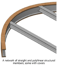
The Structural Member tool has the capability to insert straight and polylinear structural members composed of a variety of common materials and shapes, and to build networks of associated members. If a material resource is used to define a part, the material typically provides the fill, texture, physical attributes, and construction information needed for drawings, renderings, and reports. Structural members can be aligned with the layer plane or a working plane, as needed.

|
Mode |
Description |
|
Column Insertion
|
Inserts a vertical member |
|
Linear Insertion
|
Inserts a linear member |
|
Poly Insertion
|
Draws a structural member using the selected polyline creation options |
|
Column Height |
For columns with both the Start Bound and End Bound set to Layer Elevation in Structural member settings, enter the column height |
|
Polyline creation options |
For Poly Insertion mode, selects the method for drawing the polyline upon which the object is based; see Creating polylines |
|
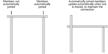
Auto Join Members
|
When selected, automatically joins connected members and maintains the association between the member being moved and adjoining members; members can be joined to another member’s start or end point, centerline or edge. Associations are maintained for copied and duplicated objects, including objects moved to a different document. |
|
Structural Member Style |
Opens the Resource Selector to select a structural member style for placement; double-click a resource to activate it |
|
Preferences
|
Opens the Structural Member Preferences dialog box to set the default preferences for structural members |
To create a structural member:
Click the tool and insertion mode. For Column Insertion mode, enter the Column Height on the Tool bar.
Do one of the following:
Click Structural Member Style on the Tool bar to select a resource from the Resource Selector.
Click Preferences to open the Structural Member Settings dialog box and specify the tool’s default parameters (see Structural member settings).
Most parameters can be edited later from the Object Info palette.
In the drawing area, if Auto Join Members mode is enabled, as you move the cursor over an existing structural member, the object is highlighted, indicating that it can be associated.
Depending on the selected insertion mode, do one of the following:
For Column Insertion mode, click to place the structural member; it is inserted by its base.
For Linear Insertion mode, click to place the structural member’s start point, and click again to place the end point.
In Linear Insertion mode, the Data bar offers additional parameters to help draw and place the structural member accurately. Press the Tab key to access the Data bar and set the Span, Angle, Pitch, Length, and/or Height. These interdependent parameters can be edited later in the Object Info palette; see Reshaping structural members for more information about these settings.
For Poly Insertion mode, click to set the starting point of the structural member, and then click to set each polyline vertex. Double-click to finish creating the structural member. For information on using the polyline creation options, see Creating polylines.
Optionally, create a style resource from the object (see Custom plug-in object styles without catalog options).
