 Structural member settings
Before the structural member is inserted, default parameters can be set in the Structural Member Preferences dialog box accessed from Preferences on the Tool bar. The parameters can also be edited for a selected structural member by clicking Settings in the Object Info palette; many, but not all, parameters can be edited directly in the Object Info palette.
To set the structural member settings:
Click to how/hide the parameters.Click to how/hide the parameters.
|
Parameter |
Description |
|
Style |
To create a custom structural member, leave the Unstyled setting. To use an existing object style from the resource libraries, click Style; from the Resource Selector, double-click a resource to activate it. |
|
Convert to Unstyled |
If a Style is currently set, select this option to convert the object to unstyled; the current values are retained, but all parameters on all tabs are set to By Instance to allow editing |
|
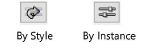
By Style/Instance |
A graphic indicates whether each parameter is set to By Style and given a fixed value or set to By Instance and editable in the dialog box. An object style may have a combination of both settings, to balance the need for consistency and flexibility. By Style/Instance settings are established by the style and cannot be changed from the preferences or settings dialog box.
To edit the object style, see Editing plug-in object styles; editing the style modifies all plug-in objects in the file that use the style. |
Structural member settings: Profile tab
Click to show/hide the parameters.Click to show/hide the parameters.
Structural member settings: Geometry tab
Click to show/hide the parameters.Click to show/hide the parameters.
|
Parameter |
Description |
|
Alignment |
All associations and end conditions are based on the centerline that controls 2D/3D representations; the alignment can be shifted to allow accurate placement of the member |
|
Profile Rotation |
Specifies an angle to rotate the structural profile about the member’s centerline axis |
|
Axis Alignment |
Select the axis alignment; the alignment graphic indicates where the axis alignment point is located |
|
Offset Y’/Z’ |
Enter the offset, if needed |
|
Elevation |
The elevation of the start and end points can be explicitly set, in reference to the story or layer |
|
Height |
Enter the difference between the start point elevation and the end point elevation. This parameter interacts with the Span, Angle, Pitch, and Length parameters that can be entered in the Data bar when a linear insertion type structural member is created and/or edited in the Object Info palette. Changing those parameters may also change the Height. See Reshaping structural members for more information about these settings. |
|
Start/End Bound |
Select the reference for the start/end point. The elevation start and end bounds must be set separately for Column Insertion mode than for Linear Insertion and Poly Insertion modes. |
|
Start/End Offset |
Enter the start/end offset, if needed |
|
Start Condition/End Condition |
The offset, miter, and bevel of an end can be set manually or automatically derived from an associated structural member. Values entered for associated members apply as an addition to the automatically determined values. |
|
Start/End Condition |
Select whether to set the start/end conditions automatically by association, manually (custom), or to snap them to horizontal or vertical. |
|
Start/End Offset |
Set the offset, if needed to establish clean member connections; the offset is the distance to the end of the member geometry from the end of the centerline curve |
|
Start/End Miter |
Set a start/end miter angle of 70° or less |
|
Start/End Bevel |
Set a start/end bevel angle of 70° or less |
Structural member settings: 2D Attributes tab
Click to show/hide the parameters.Click to show/hide the parameters.
|
Parameter |
Description |
|
Cut Plane |
|
|
Use layer cut plane elevation |
When the design layer cut plane is enabled (see Setting design layer properties), select to use the same cut plane elevation as the design layer |
|
Cut Plane Elevation |
When the design layer's cut plane elevation is not used, enter the elevation |
|
Set Attributes by |
Select whether to set attributes for the object in the Attributes palette, or by class, by line style, or by material (if a material is used). Fills and line color may not be supported for line style. |
|
Above/At/Below Cut Plane |
If attributes are set by class or line style, select the class/set the attributes for the structural member. Structural members show uniform 2D attributes for the entire object, unlike other objects which can show separate attributes at the cut plane elevation. |
|
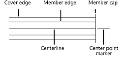
Use center mark |
Displays a center point marker at the end of the member; set the length of the marker and size of the gap, if needed. If attributes are set by class or line style, set the attributes. |
|
Caps |
Displays start and/or end caps for the member. When the cap is turned off for an end that is associated with the edge of another member, a gap is drawn in the edge of the connected member. |
Structural member settings: 3D Attributes tab
Click to show/hide the parameters.Click to show/hide the parameters.
|
Parameter |
Description |
|
Set Attributes by |
Select whether to set attributes for the member and the cover by object in the Attributes palette, by class, or by material (if a material is used); if by class, select the class. |
