Using an image in a texture shader
Import images into Vectorworks to create any type of texture shader. Multiple image shaders can be combined to create a realistic texture. For example, import an asphalt image, and then add an image bump to the asphalt. Image-based shaders can also be combined with non image-based shader types for a variety of effects.
Vectorworks supports the following image formats: BMP, JPG, PCT, PNG, PNT, PSD, QTI, SGI, TIF, TGA. Most image-based textures are automatically compressed when imported. Imported JPG files retain the original JPG data; all other image files are compressed using lossless PNG format. An image-based shader is applied to the surface of an object, similar to a wrapped shader.
To import an image for use as an image-based shader:
Create a new texture as described in Creating a new texture. From any of the four shader component lists, select the Image shader type.
The Bricks and Grass shader options include their own image selection functionality; see Color shader parameters.
The Choose Image dialog box opens; select the image to use. You can import a new image or reuse an image from an existing resource.
The next dialog box that opens depends on the type of shader, as described in the following sections.
Color shader
Color shaders can use images for image color and as a filtered image. The image color shader can display the image as-is, or can tint the image with a specified color.
From the Edit Image Color dialog box, specify the shader properties.
Click to show/hide the parameters.Click to show/hide the parameters.
|
Parameter |
Description |
|
Image preview |
Edits to the image are displayed in the image preview |
|
Change Image |
Selects a different image for import |
|
Image Effects |
Opens the Image effects dialog box, to quickly and easily adjust the image’s appearance |
|
Flip H/V |
Flips the image horizontally or vertically |
|
Rotate |
Rotates the image 90° counter-clockwise |
|
Invert |
Produces a negative of the image |
|
Tile Image |
Repeats the image in the horizontal, vertical, or horizontal and vertical directions; deselect for no tiling |
|
Filter Color |
|
|
No filter |
Does not change the image with a filter color |
|
Use Object Fill |
Filters the color of the image by the fill color selected for the object (can be different for each object that is textured by this texture) |
|
Use Chosen Color |
Tints the image with the selected color; click the color box to choose a filter color for the image |
Reflectivity shader
From the Edit Image Reflectivity dialog box, specify the shader properties.
Click to show/hide the parameters.Click to show/hide the parameters.
|
Parameter |
Description |
|
Image preview |
Edits to the image are displayed in the image preview |
|
Change Image |
Selects a different image for import |
|
Flip H/V |
Flips the image horizontally or vertically |
|
Rotate |
Rotates the image 90° counter-clockwise |
|
Invert |
Produces a negative of the image |
|
Reflection (%) |
Sets the amount of reflection. Generally, white pixels are the most reflective, while colored pixels reflect in their color. |
|
Blurriness (%) |
Sets how blurry the reflection appears. A range of 0–40% is typical. |
Transparency shader (Image option)
From the Edit Image Transparency dialog box, specify the shader properties.
Click to show/hide the parameters.Click to show/hide the parameters.
|
Parameter |
Description |
|
Image preview |
Edits to the image are displayed in the image preview |
|
Change Image |
Selects a different image for import |
|
Flip H/V |
Flips the image horizontally or vertically |
|
Rotate |
Rotates the image 90° counter-clockwise |
|
Invert |
Produces a negative of the image |
|
Index of Refraction |
As light moves through a medium, the index measures the change in the direction of the light’s rays. An index of 1.0 indicates none; a typical value for water and ice is 1.3, and for glass use 1.5–1.6. |
|
Blurriness (%) |
Sets image blurring when rendered in Final Quality Renderworks or Custom Renderworks (with Blurriness selected) |
|
Absorption Color |
Click the color box to select a color that the object may absorb differently, making it appear tinted by that color |
|
Absorption Distance |
Defines the distance rays of light have to travel before Absorption Color replaces the image color. The lower the value, the more intense the Absorption Color is. |
See Transparency shader parameters for more details.
Transparency shader (Image Mask option)
From the Create Mask dialog box, select the source for the mask.
Grayscale Pixels: darker pixels will be more transparent
Transparent Color: the color you select will be transparent
Alpha Channel: if available, the alpha channel transparency will be used
If Transparent Color is selected, the Create Transparent Color Mask dialog box opens.
The source image must be more than eight-bit color to create a transparent color mask. Images with a monochrome background are easiest to use when creating a mask transparency.
Click to show/hide the parameters.Click to show/hide the parameters.
|
Parameter |
Description |
|
Source Image |
Displays the imported image. Select the transparent color by clicking a color in the image; the resulting mask is displayed in the Transparent Color Mask preview. If necessary, use the mouse scroll wheel to zoom into and out of the image, or click and hold the mouse wheel button to pan. |
|
Transparent Color |
Displays the current transparent color. Either click the source image to designate the transparent color, or select the color by clicking the color box. |
|
Transparent Color Mask |
Displays a preview of the mask based on the current transparent color selection and settings; in the preview black pixels are transparent, and white pixels are opaque |
|
Color Matching Tolerance |
Adjusts the transparency tolerance; drag the slider to the right to increase the tolerance level. This allows a wider range of pixels similar to the transparent color to be considered transparent. |
|
Mask Contrast |
Adjusts the mask edge contrast; increase the edge contrast sharpness by dragging the slider to the right. Soften the contrast by dragging the slider to the left. |
From the Edit Image Mask dialog box, specify the shader properties.
Click to show/hide the parameters.Click to show/hide the parameters.
|
Parameter |
Description |
|
Change Image |
Selects a different image for import |
|
Transparent Color Mask |
Edits the transparent color mask settings |
|
Flip H/V |
Flips the image horizontally or vertically |
|
Rotate |
Rotates the image 90° counter-clockwise |
|
Invert |
Produces a negative of the image; useful for swapping the opaque and transparent areas of a grayscale mask |
|
Horizontal/Vertical Repetitions |
Specifies the number of repetitions of the mask shader in the horizontal and vertical direction |
|
Single |
The mask shader does not repeat; it is only shown once (this is the typical setting, especially for decals) |
|
Infinite |
The mask shader repeats infinitely in the horizontal and/or vertical direction |
|
Custom |
The mask shader repeats the specified number of times |
|
Opacity (%) |
Enter the opacity percentage; values less than 100 create a partially transparent mask |
|
Anti-Aliased |
Smooths the edges of the image mask |
Bump shader
From the Edit Image Bump dialog box, specify the shader properties.
Click to show/hide the parameters.Click to show/hide the parameters.
|
Parameter |
Description |
|
Image preview |
Edits to the image are displayed in the image preview |
|
Change Image |
Selects a different image for import |
|
Flip H/V |
Flips the image horizontally or vertically |
|
Rotate |
Rotates the image 90° counter-clockwise |
|
Invert |
Produces a negative of the image; useful for reversing the high and low pixels for a bump image |
|
Bump Strength (%) |
Sets the amplitude of the bump shader. Positive and negative values can be entered. A value of 10% would result in a mild bumpy appearance. |
|
Parallax Offset (%) |
Sets the amplitude of the parallax mapping. Positive and negative values can be entered. Parallax mapping enhances bump mapping by giving textures such as bricks more apparent depth, without the performance slowdown that can be associated with displacement mapping. Unlike displacement mapping, parallax mapping appears flat in silhouette. |
|
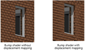
Displacement Mapping |
For realistic bump textures, displacement mapping creates texture and bumpy details with a rendering technique that appears embossed, projecting the geometry outward from the surface.
This mapping applies only to Final Quality Renderworks, and to Custom Renderworks when Displacement Mapping is enabled in the render options. Rendering can be significantly slower with displacement mapping. If the image bump does not provide the desired results, try a noise bump shader. |
|
Height |
Specify a non-zero height to enable displacement mapping; large height values may result in longer render times |
|
Detail |
Sets the level of detail for displacement mapping; requirements and results vary depending on the texture and the surface’s face size. Textures without too much bump detail and a large face size, such as boards or stones, render with less detail and can be set with a lower level of detail; fine, faceted textures like grass or leaves may require a high level of detail, which also requires more rendering time. Conversely, very large surfaces, like a ground plane, may need higher levels of detail to see the displacement. |
|
Self-Shadowing |
Adds shadows to the displaced geometry, increasing realism as well as rendering time |
When you use the monochromatic textures provided with Vectorworks, the Bump Strength parameter may require careful adjustment depending on the viewing distance from the model.
Due to compression artifacts, JPG images generally do not work well as bump images. PNG and TIF compression works well for bump images; when importing images, select PNG rather than JPG as the compression method.
