Advanced sheet layer viewport properties
To access additional sheet layer viewport parameters, click Advanced Properties from the Object Info palette or Properties dialog box of a selected viewport. The Advanced Viewport Properties dialog box opens. These settings affect the viewport display only; they do not change the original design layer(s).
Click to show/hide the parameters.Click to show/hide the parameters.
|
Parameter |
Description |
|
Line Weight Scale |
Enter a value larger than 1.0 to increase the viewport line weights, or a value below 1.0 (but larger than 0) to decrease the line weights |
|
Line Type Scale |
Enter a value larger than 1.0 to increase the length and spacing of viewport line type segments, or a value below 1.0 (but larger than 0) to decrease the length and spacing of line type segments |
|
Hatch Line Scale |
Enter a value larger than 1.0 to increase the spacing between viewport hatch lines, or a value below 1.0 (but larger than 0) to decrease the spacing between hatch lines |
|
Text Scale |
Enter a value larger than 1.0 to increase the text size in viewports, or a value below 1.0 (but larger than 0) to decrease the text size; only associated viewport text is affected. Graphic objects that are part of the text item, such as a reference marker container or detail callout bubble, are scaled with the text. Dimensional objects inside plug-in objects, such as dimensions within a bubble grid object, are not scaled. Plug-in objects, such as a North arrow object, are not scaled if they have been placed while editing the viewport in Edit Annotation mode. |
|
Marker Scaling |
Select whether markers (such as those found on dimensions, callouts, or other types of annotations) scale automatically according the scale of the viewport, or maintain a fixed scale |
|
Auto Scale |
Automatically scales markers based on the viewport scale factor; for example, if a marker is on a layer with a scale 1:50 and the sheet layer viewport has a scale of 1:200, the marker will auto scale to 1:4 |
|
Custom Scale |
Sets a scale factor for markers in the viewport |
|
Scale |
Set the scale factor for markers; a scale factor below 1.0 decreases the size of the marker relative to its definition at a 1:1 scale, while a factor above 1.0 increases its size |
|
Page Symbol Scaling |
These settings affect page-based symbols in the viewport (see Concept: Vectorworks symbols) |
|
Symbol Scale |
Sets a scale factor for page-based symbols; a scale factor below 1.0 decreases the size of the symbol relative to its definition at a 1:1 scale, while a factor above 1.0 increases its size |
|
Attribute Scaling |
These settings affect the attributes (such as line weight) of page-based symbols in the viewport |
|
Use Symbol Factor |
Uses the Symbol Scale factor to scale the attributes |
|
Use Individual Factors |
Uses the other, individual scale factors in the Advanced Properties dialog box, such as the Line Weight Scale, to scale the page-based symbol attributes |
|
Display with Clip Cube |
If the viewport already has an associated clip cube, this options displays the existing clip cube. If the viewport does not have an associated clip cube, this option creates a clip cube that bounds all visible objects. Access the clip cube to change its dimensions when editing the viewport’s design layer. |
|
Cap Fill/Edge Color |
Select the fill and edge colors for the cut lines created by the clip cube crop; these settings override the Vectorworks preference for these attributes to maintain a consistent appearance when the sheet layer is viewed by different users |
|
Cast Shadows of Removed Objects |
When rendering, includes shadows cast by objects that are not included in the viewport, for a more realistic effect (especially for interior elevations) |
|
Render Gray Layers Transparent |
Design layers with a visibility set to “Gray” are rendered as transparent |
|
Black and white only |
Changes all colors in the viewport to black or white; this is useful for displaying two viewport copies on the same sheet layer, with one in color and the other in black and white. However, if the document preferences display setting is black and white, viewports will also display as black and white even if this option is deselected. A viewport data visualization (Design Suite product required) overrides this option. |
|
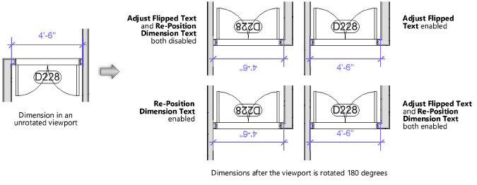
Adjust Flipped Text |
Re-orients rotated and flipped text in the viewport so that it is always readable. The text box stays in the rotated and flipped position relative to the dimension line, but the text itself is re-oriented. (This setting overrides the flipped text preference for the document; see Document preferences: Display tab.) |
|
Re-Position Dimension Text |
Re-positions rotated and flipped dimension text in the viewport according to the text position in the dimension standard. The text itself stays in the rotated and flipped orientation, but the text box position relative to the dimension line is changed. (This setting overrides the flipped text preference for the document; see Document preferences: Display tab.) |
|
None fill uses Alpha Transparency |
Displays Shaded render mode and Renderworks viewports with alpha channels so white pixels are not transparent when the fill style is set to None; on Windows, the Use GDI+ imaging Vectorworks preference must be enabled |
|
Drop Shadows |
Displays any drop shadow attributes added to objects in the original design layer; this setting does not affect drop shadows applied to the viewport object itself |
|
Preview |
Displays the viewport with a preview of the advanced settings |